Temperature and humidity meter with lamp and mirror

A technology of thermo-hygrometer and mirror, which is applied to lighting and heating equipment, parts of lighting devices, casings of measuring devices, etc., which can solve the problem of single function of thermo-hygrometer

Inactive Publication Date: 2014-09-10
XIAN SANWEI SECURITY TECH
View PDF0 Cites 1 Cited by
  • Summary
  • Abstract
  • Description
  • Claims
  • Application Information

AI Technical Summary

Problems solved by technology

[0003] The purpose of the present invention is to overcome the problem of single function of the existing thermo-hygrometer

Method used


Image

  • Temperature and humidity meter with lamp and mirror

Examples


Embodiment 1

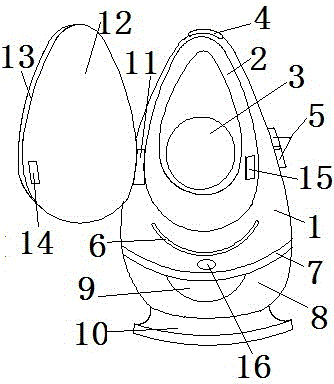
[0012] This embodiment provides a temperature-hygrometer with a lamp and a mirror, including a housing 1, a cut surface 2, a display screen 3, and a reminder light 6. The cut surface 2 is in the shape of a drop, and the display screen 3 is at the bottom of the cut surface 2. 3 is coplanar with the cut surface 2, and the reminder light 6 is located on the casing 1 below the cut surface 2. When the indoor temperature and humidity are not up to standard, it will automatically light up to remind the user to adjust the indoor temperature and humidity in time. The bottom of the casing 1 An isolation layer 7 is provided, a light control switch 16 is arranged between the isolation layer 7 and the reminder light 6, a lamp 9 is arranged in the middle of the interior of the isolation layer 7, a lampshade 8 is connected to the periphery of the isolation layer 7, and a lampshade 8 is arranged at the bottom of the lampshade 8. The base 10 and the isolation layer 7 have played the role of hea...

Embodiment 2

[0015] On the basis of Embodiment 1, the lamp 9 and the light control switch 16 provided by this embodiment are electrically connected to the internal circuit of the temperature-hygrometer through wires, and people can turn on the temperature-hygrometer by pressing the light control switch 16. In the night light mode, the lampshade 8 is made of PC material; the frame 12, the mirror 13 and the cut surface 2 are equal in size and are all drop-shaped.

[0016] When the present invention is in use, it is placed in a room where the temperature and humidity need to be controlled. If the temperature and humidity in the room are normal at ordinary times, the prompt light 6 will not light up, and the mirror frame 12 can be buckled by the attraction force of the small iron sheet 14 and the small magnet 15. Close on the cut surface 2, when the prompt light 6 is on, open the frame 12, adjust the indoor temperature and humidity according to the value displayed on the display screen 3 covere...


PUM


Abstract

The invention provides a temperature and humidity meter with a lamp and a mirror. The temperature and humidity meter comprises a shell, a tangent plane, a display screen and a prompting lamp. The tangent plane presents to be water-drop-shaped. The display screen is arranged at the bottom end of the tangent plane. The display screen and the tangent plane are coplanar. The prompting lamp is arranged on the shell below the tangent plane. The bottom part of the shell is provided with an isolation layer. A lamp control switch is arranged between the isolation layer and the prompting lamp. The middle of the internal part of the isolation layer is provided with the lamp. The periphery of the isolation layer is connected with a lamp cover. The bottom end of the lamp cover is provided with a pedestal. The lower left side of the tangent plane is provided with a rotating shaft. The other end of the rotating shaft is connected with a mirror frame. The external side of the mirror frame is provided with the mirror. The left part of the internal side of the mirror frame is provided with a small iron sheet. The tangent plane, which is corresponding to the small iron sheet, is provided with a small magnet. Advantages of the temperature and humidity meter are that the mirror and the like are arranged so that functions of the temperature and humidity meter are increased, people can model in the mirror via the temperature and humidity meter which can also act as a small night lamp, indoor temperature and humidity can also be monitored simultaneously, and convenience is provided for people.

Description

technical field [0001] The invention belongs to the technical field of electronic products, and in particular relates to a temperature-hygrometer with a lamp and a mirror. Background technique [0002] The existing thermo-hygrometer has a simple structure, which provides reference data for people to control the indoor temperature and humidity. People can adjust the indoor humidity through humidification or ventilation according to the temperature and humidity value displayed on the thermo-hygrometer, and adjust the indoor humidity through air conditioning. Temperature, so that the indoor temperature and humidity can reach the value that is most conducive to improving the work efficiency of users, or the value that is most conducive to the health of babies. The temperature and humidity are the most suitable temperature and humidity. People can adjust the indoor temperature and humidity in time through the reminder of the indicator light, so they don’t have to constantly look ...

Claims


Application Information

Patent Timeline
Patent Type & Authority Applications(China)
IPC IPC(8): G01D21/02G01D11/24G01D11/28F21V33/00
Inventor 贾卫东魏军锋
Owner XIAN SANWEI SECURITY TECH
Why Eureka
Try Eureka