
X-ray sources for differential phase-contrast imaging with x-ray gratings

A differential phase contrast and X-ray technology, which is applied in the field of X-ray imaging, can solve problems such as high cost, difficult absorption grating manufacturing process, and limited field of view, and achieve large emission current, overcome image quality degradation, and wide radiation field of view Effect

Active Publication Date: 2016-10-05
SHENZHEN UNIV
View PDF7 Cites 0 Cited by
  • Summary
  • Abstract
  • Description
  • Claims
  • Application Information

AI Technical Summary

Problems solved by technology

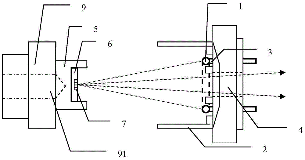
[0006] The technical problem to be solved by the present invention lies in that, in the existing array X-ray source adopting absorption grating mode, the defect that the absorption grating manufacturing process is difficult and the cost is high, and the X-ray source adopting an array structure anode target is affected by the imaging field of view. To overcome the defects that are difficult to apply to large-field phase-contrast imaging, a new type of X-ray source that is relatively simple in structure, simple in manufacturing process, and low in cost for high-energy X-ray phase-contrast imaging is provided. Since the outgoing X-rays have no axial distribution Completely solve the problem of limited field of view

Method used


Image

  • X-ray sources for differential phase-contrast imaging with x-ray gratings
  • X-ray sources for differential phase-contrast imaging with x-ray gratings
  • X-ray sources for differential phase-contrast imaging with x-ray gratings

Examples


Embodiment Construction

[0039] In order to have a clearer understanding of the technical features, purposes and effects of the present invention, the specific implementation manners of the present invention will now be described in detail with reference to the accompanying drawings.

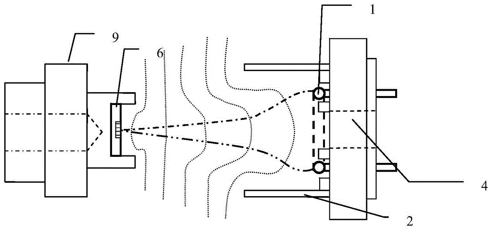
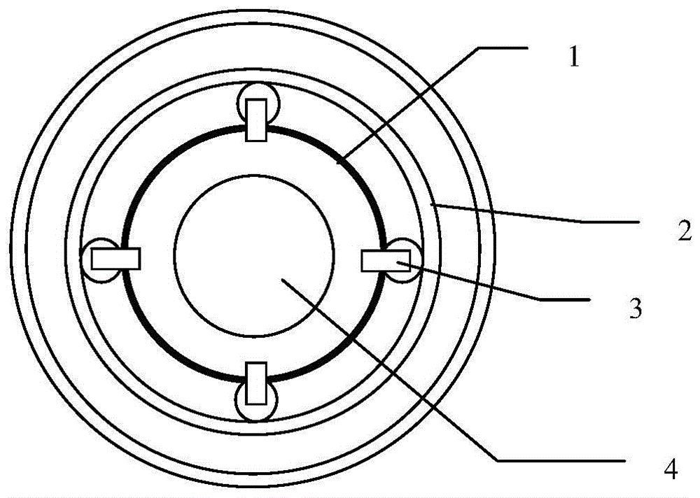
[0040] like Figure 1-6 As shown, an X-ray source for X-ray grating differential phase contrast imaging includes an annular cathode 1 for emitting electron beams, an anode target 6 for emitting X-rays in response to the incident electron beams, and an anode target 6 for accelerating and converging The electrode structure of the electron beam, the cathode heating power supply (not shown) for heating the annular cathode 1; the annular cathode 1 is arranged opposite to the target surface of the anode target 6, and the corresponding annular cathode 1 is arranged behind the annular cathode 1 The X-ray exit window 4 in the middle position and parallel to the target surface of the anode target 6; the target surface of the anod...


PUM

PropertyMeasurementUnit
radiusaaaaaaaaaa
thicknessaaaaaaaaaa
diameteraaaaaaaaaa

Abstract

The invention discloses an X-ray source for X-ray grating differential phase contrast imaging, comprising a ring-shaped cathode, an anode target, an electrode structure, a cathode heating power source and an electrode structure power source; An X-ray emission window corresponding to the middle position of the annular cathode and parallel to the target surface of the anode target is arranged behind the cathode; the target surface of the anode target is perpendicular to the optical axis direction of the emitted X-ray; the electrode structure includes a cathode sleeve and an anode sleeve The anode target is arranged in the anode sleeve; the annular cathode is arranged in the cathode sleeve; the target surface of the anode target is provided with an array structure composed of two different materials periodically and alternately, and the two different materials are respectively made of two different materials. Substances formed from elements with widely different atomic numbers. The present invention provides a novel X-ray source with relatively simple structure and applied to high-energy X-ray phase contrast imaging. Since the outgoing X-rays have no axial distribution, the problem of limited field of view is completely solved.

Description

technical field [0001] The invention belongs to the technical field of X-ray imaging, and relates to an X-ray source, in particular to an X-ray source for large-field X-ray phase-contrast imaging. Background technique [0002] X-ray imaging technology is widely used in medicine, life science, material science and industrial non-destructive detection and other fields. Traditional X-ray imaging technology is based on the absorption and attenuation characteristics of the object to X-rays. It requires that the difference in the absorption attenuation coefficient between the object and the surrounding environment and different components in the object is relatively obvious. The imaging effect is remarkable when detecting objects made of heavy elements such as metals, such as bone imaging in medical imaging, metal detection in industrial inspection, etc. For materials based on light elements (carbon, hydrogen, oxygen, etc.) and biological soft tissues such as blood vessels and ar...

Claims


Application Information

Patent Timeline
Patent Type & Authority Patents(China)
IPC IPC(8): G01N23/04A61B6/03
Inventor 牛憨笨李冀黄建衡
Owner SHENZHEN UNIV
Learn More