Lens actuating device

A technology of lens actuation and moving parts, which is applied in installation, optics, instruments, etc., and can solve problems such as coils and magnetic bodies occupying a large space

Inactive Publication Date: 2014-09-10
WAH HONG INDAL CORP
View PDF7 Cites 7 Cited by
  • Summary
  • Abstract
  • Description
  • Claims
  • Application Information

AI Technical Summary

Problems solved by technology

However, the radial arrangement of the coil and the magnetic body in this way will occupy a large space

Method used


Image

  • Lens actuating device
  • Lens actuating device
  • Lens actuating device

Examples


no. 1 example

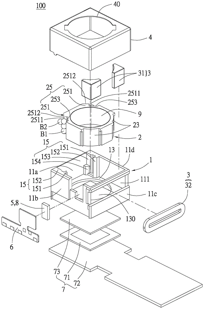
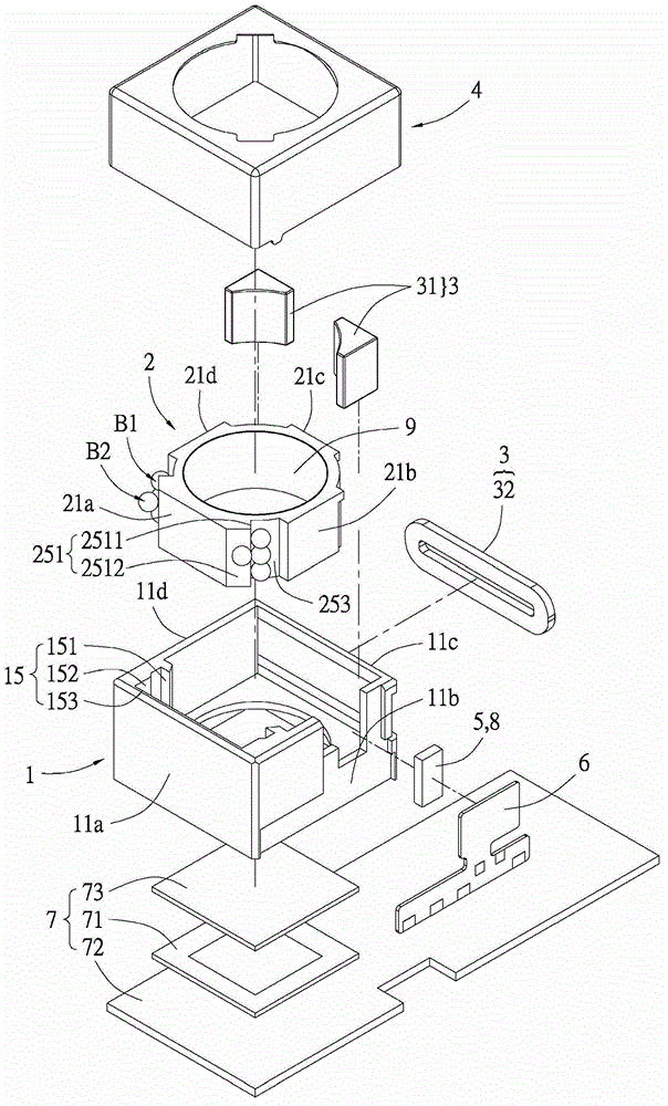
[0056] Please refer to figure 1 and figure 2 , is an exploded perspective view of the lens actuator device of the present invention. The present invention provides a lens actuating device 100, which includes a fixed part 1, a moving part 2, a driving unit 3 for providing driving force of the moving part 2, and a driving unit 3 for guiding and restricting the moving part 2 along the optical axis. A mobile supporting unit that moves in a direction, an outer cover 4 , a position sensing element 5 and a lateral traction element 6 . The above-mentioned moving part 2 is movably disposed in the fixing part 1 along the optical axis direction, and the moving part 2 is installed with a lens module 9 . The driving unit 3 is disposed between the fixing part 1 and the moving part 2 . The above optical axis direction refers to the axial center direction of the lens module 9 .

[0057] In this embodiment, in order to make the moving part 2 and its lens module 9 move accurately along the...

no. 2 example

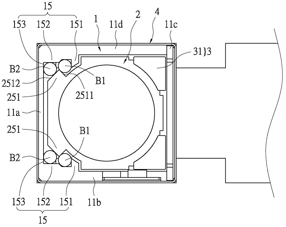
[0081] In the above embodiment, there are two rows of balls B1 and B2 at the two corners to hold the second guide structure 25 to provide forces in different directions to guide the moving part 2 to be correctly displaced on the optical axis. Therefore, there are four rows of spheres in order to achieve a better balance. However, as a supplementary note, in the present invention, the above-mentioned first and second guiding structures may be provided only at one corner, and only one column may be provided at the other corner, so as to achieve auxiliary balance.

[0082] Based on the above, the second embodiment of the present invention only uses three rows of spheres to achieve the above functions. see Figure 6 In this embodiment, a receiving groove 255 is arranged on the moving part 2, roughly corresponding to the middle of the first side wall 11a, and the receiving groove 225 accommodates another row of spheres B2' (in this embodiment, circular spheres). The above-mention...

no. 3 example

[0084] The difference from the second embodiment is that the rolling element R2 of this embodiment is cylindrical, and for matching the rolling element R2, this embodiment has a wider receiving groove 255'.


PUM


Abstract

The invention relates to a lens actuating device comprising a fixed part, a moving part, a driving unit, and a mobile support unit. The moving part is arranged in the fixed part movably along the direction of the optical axis; and a lens module is installed at the moving part. The driving unit is arranged between the fixed part and the moving part and is located at one side of the moving part, thereby providing a driving force of the moving part. The mobile support unit and the driving unit are located at the other side of the moving part in an opposite mode; the mobile support unit includes a first guiding structure, a second guiding structure, and a plurality of scrollable rolling elements, wherein the first guiding structure is parallel to the direction of the optical axis and is formed at the inner side of the fixed part and the second guiding structure is formed at the periphery of the moving part and corresponds to the first guiding structure; and the plurality of rolling elements are located between the first guiding structure and the second guiding structure in a two-row mode to clamp the second guiding structure, thereby limiting displacement of the moving part along the direction parallel to the direction of the optical axis.

Description

technical field [0001] The invention relates to a lens actuating device, in particular to a lens actuating device used for driving an optical mirror group. Background technique [0002] The existing camera lens actuation module uses a magnetic body and a conductive coil to be respectively arranged on the lens module and the base. A driving force is generated in the direction of the optical axis to drive the lens module to move in focus. For example, the "optical device" disclosed in Taiwan Patent No. I343165, which has been approved by the applicant of this case, has a lens, a coil located on one side of the lens, and a magnetic body. There is a guide rod between the lens and the coil. The lens is guided by the above-mentioned guide rod and driven by the coil and the magnetic body to move forward and backward in the direction of the optical axis. However, radial arrangement of the coil and the magnetic body in this way will occupy a large space. [0003] Based on the abov...

Claims


Application Information

Patent Timeline
IPC IPC(8): G02B7/04
Inventor 卓英吉郭利德
Owner WAH HONG INDAL CORP
Why Eureka
Try Eureka