Pixel driving circuit, driving method thereof, and display device
A technology of a pixel driving circuit and a driving method, which is applied to static indicators, instruments, etc., can solve the problems of brightness difference of display devices, affecting the screen display effect, inconsistency, etc., so as to solve the inconsistency of threshold voltage, improve the screen display effect, and offset the work. effect of current
- Summary
- Abstract
- Description
- Claims
- Application Information
AI Technical Summary
Problems solved by technology
Method used
Image
Examples
Embodiment 1
[0035] This embodiment provides a pixel driving circuit, including: a driving transistor and an organic light emitting diode connected to the driving transistor. The pixel driving circuit further includes: a first switching tube connected to the driving transistor, and the first switching tube is controlled by the first A scanning signal connected to the power supply voltage; a storage capacitor connected to the driving transistor; a second switching tube connected to the storage capacitor, the second switching tube is controlled by the second scanning signal and connected to the data voltage; connected to the driving transistor and the third switch tube between the common end of the first switch tube and the common end of the drive transistor and the storage capacitor, the third switch tube is controlled by the third scan signal; the third switch tube connected to the common end of the drive transistor and the organic light emitting diode Four switch tubes, the fourth switch t...
Embodiment 2
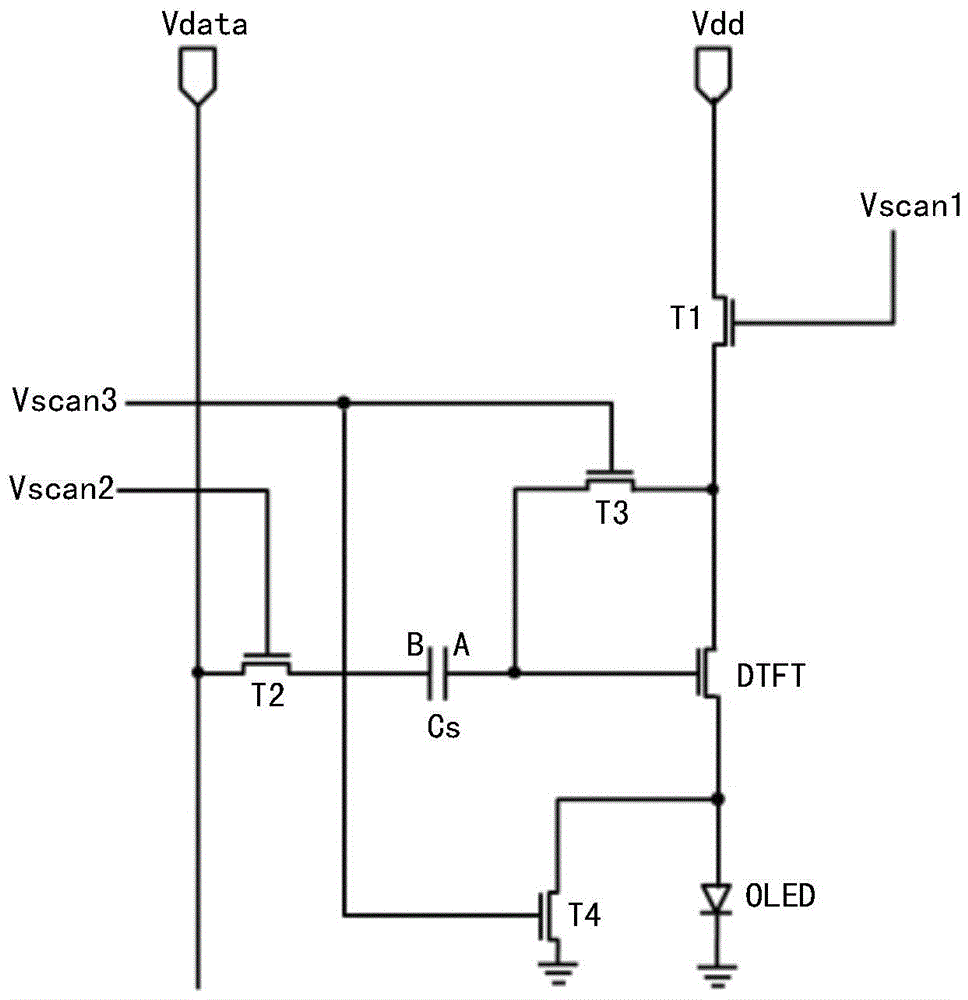
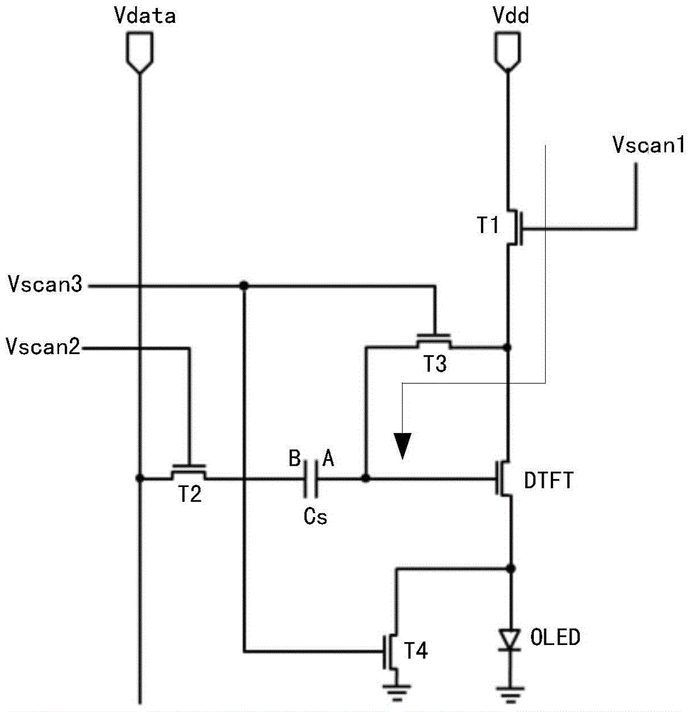
[0039] Based on Embodiment 1, this embodiment specifically provides a pixel driving circuit, such as figure 2 As shown, the circuit includes: an organic light emitting diode OLED, a driving transistor DTFT, a first switching tube T1, a second switching tube T2, a third switching tube T3, a fourth switching tube T4 and a storage capacitor Cs.
[0040] The connection relationship between the above components is the same as that of the pixel driving circuit described in Embodiment 1, and the more specific connection relationship can preferably be as follows:
[0041] The organic light emitting diode OLED is connected with the output terminal of the driving transistor DTFT.
[0042] The control end of the first switching tube T1 is connected to the first scanning signal Vscan1, the input end is connected to the power supply voltage Vdd, and the output end is connected to the input end of the driving transistor DTFT.
[0043] The control end of the second switching transistor T2 ...
Embodiment 3
[0076] When the types of the first switch tube and the second switch tube are different, the first scan signal and the second scan signal are the same, and the first switch tube and the second switch tube can preferably be connected to the same scan line. Based on this, this embodiment provides a pixel driving circuit, the structure of which is as follows Figure 8 As shown, the first switching transistor T1 and the second switching transistor T2 are connected to the same scanning line and controlled by the same scanning signal. At this time, the type of the first switching transistor T1 may be N-type, and the type of the second switching transistor is P-type; or the type of the first switching transistor T1 may be P-type, and the type of the second switching transistor is N-type.
[0077] The driving method of the pixel driving circuit provided in this embodiment is the same as the driving method introduced in the first embodiment, and will not be repeated here.
[0078] If ...
PUM
 Abstract
Description
Claims
Application Information
 - R&D
- Intellectual Property
- Life Sciences
- Materials
- Tech Scout
- Unparalleled Data Quality
- Higher Quality Content
- 60% Fewer Hallucinations
Browse by: Latest US Patents, China's latest patents, Technical Efficacy Thesaurus, Application Domain, Technology Topic, Popular Technical Reports.
© 2025 PatSnap. All rights reserved.Legal|Privacy policy|Modern Slavery Act Transparency Statement|Sitemap|About US| Contact US: help@patsnap.com


