LED display system and its driving circuit that can eliminate the residual image of LED display screen

A technology of LED display and LED drive, which is applied to static indicators, instruments, etc., can solve the problems of uncertain switching time of the drive module 300, burning the periphery of the circuit, and inability to cope with the application of the drive module 300, so as to improve the display effect of the screen, The effect of eliminating afterimage phenomenon

Active Publication Date: 2016-04-20
WUXI ETEK MICROELECTRONICS
View PDF6 Cites 0 Cited by
  • Summary
  • Abstract
  • Description
  • Claims
  • Application Information

AI Technical Summary

Problems solved by technology

[0005] The timing control module 101 in the above-mentioned LED display blanking control circuit 100 simply uses digital logic to realize the enabling control of the driving module 300 (that is, the switching control of the driving module 300) and the conduction and switching of the switching tubes MP1-MPn. Although the shutdown control method is simple, the disadvantage is that because the current of the drive module 300 is different under different conditions of use, the switching time of the drive module 300 is uncertain, and the timing control module 101 cannot control the drive by simply using digital logic. The time of module 300 switch is judged, therefore, if sequence control module 101 turns on the delay time setting of switching tube MP1-MPn after controlling drive module 300 to be closed too short, namely output port OUTN1-OUTNn has not been closed yet, just leads to Passing the switch tubes MP1-MPn will cause a short circuit in the channel, burn the circuit and the periphery; if the delay time is set too long, the pre-charging effect will not be achieved
That is to say, simply using digital logic to control the turn-on and turn-off of the pre-charging control switches MP1-MPn makes the blanking control circuit 100 unable to cope with the application of the driving module 300 under different usage conditions.

Method used


Image

  • LED display system and its driving circuit that can eliminate the residual image of LED display screen
  • LED display system and its driving circuit that can eliminate the residual image of LED display screen
  • LED display system and its driving circuit that can eliminate the residual image of LED display screen

Examples


Embodiment Construction

[0028] In order to make the above objects, features and advantages of the present invention more comprehensible, the present invention will be further described in detail below in conjunction with the accompanying drawings and specific embodiments.

[0029] Reference herein to "one embodiment" or "an embodiment" refers to a particular feature, structure or characteristic that can be included in at least one implementation of the present invention. "In one embodiment" appearing in different places in this specification does not all refer to the same embodiment, nor is it a separate or selective embodiment that is mutually exclusive with other embodiments. Unless otherwise specified, the words connected, connected, and joined in this document mean that they are electrically connected directly or indirectly.

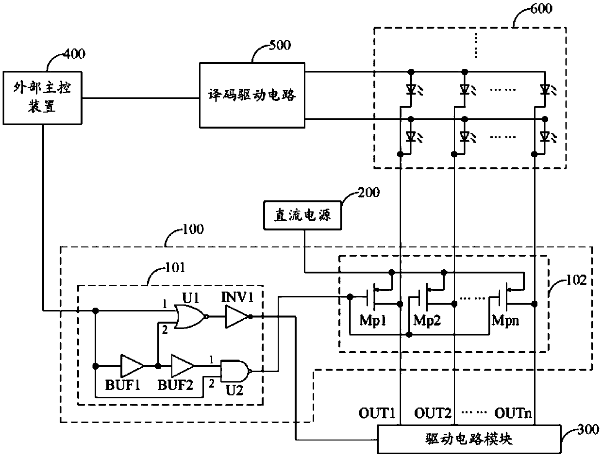
[0030] Please refer to Figure 5 As shown, it is a schematic circuit diagram of an LED display system in an embodiment of the present invention. The LED display system in...


PUM


Abstract

The invention provides an LED display system capable of eliminating a ghosting image on an LED display screen and an LED driving circuit. The LED driving circuit comprises a control logic unit and at least one column control circuit, wherein the column control circuit comprises an output driving unit, a ghosting image removing unit and a precharge switch. After a column driving control signal from the control logic unit jumps to be invalid, the output driving unit stops supplying driving current, and the output driving unit is detected by the ghosting image removing unit, so as to determine whether the output driving unit stops supplying the driving current; if the output driving unit stops supplying the driving current, a valid precharge control signal is output to control the precharge switch to be on so as to connect precharge reference voltage and a column wire; thus, the ghosting image of the LED display screen can be eliminated, and the LED driving circuit can be suitable for different driving currents.

Description

【Technical field】 [0001] The invention relates to the technical field of LED (Liquid Emitting Diode) display, in particular to an LED display system capable of eliminating afterimages on LED display screens and a driving circuit thereof. 【Background technique】 [0002] Generally, there are more or less afterimages (smearing / ghosting) in dynamic scanning LED displays, and the mechanism is due to the presence of parasitic capacitance at the chip output terminal, circuit board, and LED lamp port. When some devices are turned off at a certain moment, the corresponding parasitic capacitance will store residual charge, and the residual charge will be discharged through the channel at the next moment, so that the LED in the LED display screen that should not be lit is slightly bright, Afterimage phenomenon occurs. Please refer to figure 1 As shown, it is a schematic diagram of a partial circuit structure of an LED display screen using a 1 / 4 scan mode in the prior art. figure 1 A...

Claims


Application Information

Patent Timeline
Patent Type & Authority Patents(China)
IPC IPC(8): G09G3/32
Inventor 史良俊华竹平汪东毛成烈
Owner WUXI ETEK MICROELECTRONICS
Why Eureka
Try Eureka