Wireless data transmission network and device enabling transmission apparatuses in wireless data transmission network to transmit data frames

A technology of wireless data transmission and transmission equipment, applied in wireless communication, electrical components, etc., can solve problems such as transmission failure and waste of transmission resources, achieve the effect of reducing the number of relays, avoiding repeated relays, and increasing the transmission rate

Active Publication Date: 2014-09-10
SHANTOU GAOBO ELECTRONICS TECH
View PDF3 Cites 0 Cited by
  • Summary
  • Abstract
  • Description
  • Claims
  • Application Information

AI Technical Summary

Problems solved by technology

In order to reduce the number of relays, for example, it can be relayed successively through node devices 3 and 6, and finally reach the target device 8. However, since the wireless transmission of data frames is greatly affected by distance and environmental changes, if the relay distance i

Method used


Image

  • Wireless data transmission network and device enabling transmission apparatuses in wireless data transmission network to transmit data frames
  • Wireless data transmission network and device enabling transmission apparatuses in wireless data transmission network to transmit data frames

Examples


Embodiment 1

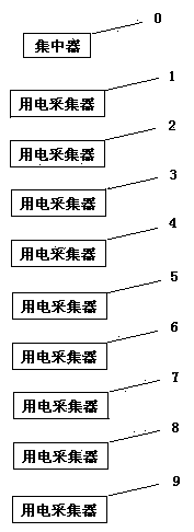
[0030] Such as figure 1 The wireless data transmission network is used for electricity data collection. Multiple power consumption collectors are installed in different communities, and each power consumption collector is connected to the smart meter cluster in the community where it is located to collect the electricity consumption data of the community. The concentrator and each electricity collector are transmission devices. The concentrator sends data to each electricity collector, and each electricity collector remits the collected data to the concentrator.

[0031] The wireless data transmission network is centered on the concentrator, and the number of the concentrator at the top of the network is 0. Starting from the concentrator, the 9 power collectors are incrementally numbered 1, 2, 3, ..., 9, these 9 electricity collectors form a communication branch. Similarly, other power consumption collectors in the network may also form other communication branches based on ...

Embodiment 2

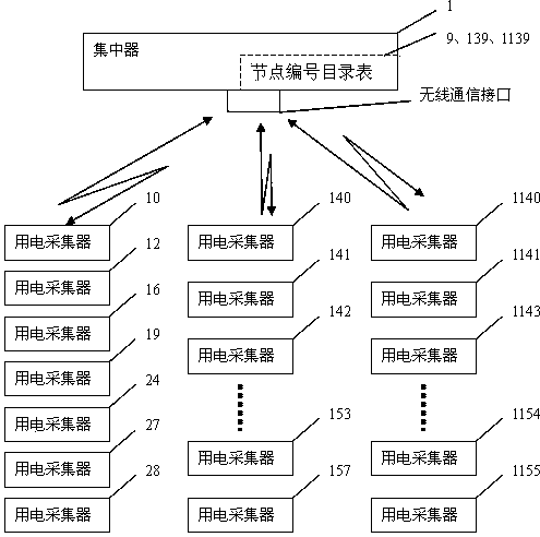
[0046] Another wireless data transmission network for electricity data collection such as figure 2 . In this embodiment, the parts not particularly described are the same as those in Embodiment 1. In this embodiment, by optimizing the serial number of the node device, a better effect is achieved in the application.

[0047] The wireless data transmission network takes the concentrator as the center, and the concentrator at the top of the network is numbered 1. Starting from the concentrator, the 7 electricity collectors arranged vertically on the left are incrementally numbered according to the distance from the concentrator 1. 10, 12, 16, 19, 24, 27, 28, these seven electricity collectors form the first communication branch, and similarly, the electricity collectors 140, 141, 142, ..., 153, 157 form the second communication branch, and the power collectors 1140, 1141, 1143, ..., 1154, 1155 arranged vertically on the right form the third communication branch, and the equipm...


PUM


Abstract

A wireless data transmission network is provided. In the network, a plurality of node apparatuses compete for the relaying of data frames; after receiving the data frames, the node apparatuses should perform time delay which is larger than or equal to 0; the nearer the geographical positions of node apparatuses in the plurality of node apparatuses are to a target apparatus, the shorter the time delay is, and if the node apparatuses receive the data frames again during the time delay, the node apparatuses do not transmit the data frames. Under the above competition rules, the node apparatuses DA of which the geographical positions are near to the target apparatus obtain a current relaying authority, and the current relaying enables a longer transmission distance, and therefore, the number of times of relaying, which is required by the data frames to reach the target apparatus, can be decreased, and node apparatuses of which the geographical positions are not near to the target apparatus, fail in the competition, and are not allowed to perform the current relaying, and therefore, repeated relaying can be avoided. In the network, a method for the transmission apparatuses to transmit the data frames is completed through a computer system which is controlled by computer program instructions.

Description

technical field [0001] The present invention relates to a wireless data transmission network and a method for transmitting data frames by a transmission device therein, in particular to a data frame relay strategy therein. The method is performed by a computer system controlled by computer program instructions. Background technique [0002] see figure 1 A transmission path composed of transmission devices 0, 1, 2, 3, 4, 5, 6, 7, 8, and 9. Taking data frames originating from the originating device 0 and finally arriving at the target device 8 as an example, they can be relayed by node devices 1, 2, 3, 4, 5, 6, and 7 in turn, and finally reach the target device 8. The most intuitive relay strategy is too many relay times and the transmission rate is too low. In order to reduce the number of relays, for example, it can be relayed successively through node devices 3 and 6, and finally reach the target device 8. However, since the wireless transmission of data frames is greatl...

Claims


Application Information

Patent Timeline
IPC IPC(8): H04W40/20H04W40/22
Inventor 林楷东蔡伟鸿蔡玲如陈银冬杨育标张纯王连城吴思驰李嘉鸿刘文胜
Owner SHANTOU GAOBO ELECTRONICS TECH
Why Eureka
Try Eureka