Electro-cardiograph Sensor Mat

A sensor pad, electrocardiogram technology, applied in the direction of sensors, electrocardiography, bioelectric signal measurement, etc., to achieve the effect of avoiding radiation

Active Publication Date: 2014-09-10
KONINKLJIJKE PHILIPS NV
View PDF5 Cites 4 Cited by
  • Summary
  • Abstract
  • Description
  • Claims
  • Application Information

AI Technical Summary

Problems solved by technology

It is thus possible to deliver detailed electrophysiological information that could only be measured during invasive electrophysiological procedures using cardiac catheterization
In add

Method used


Image

  • Electro-cardiograph Sensor Mat
  • Electro-cardiograph Sensor Mat
  • Electro-cardiograph Sensor Mat

Examples


Embodiment Construction

[0060] In the following, similar elements are denoted by the same reference numerals.

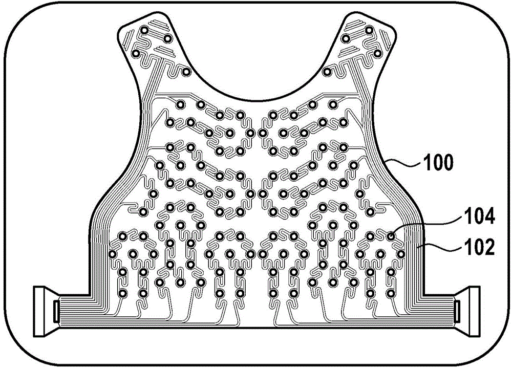
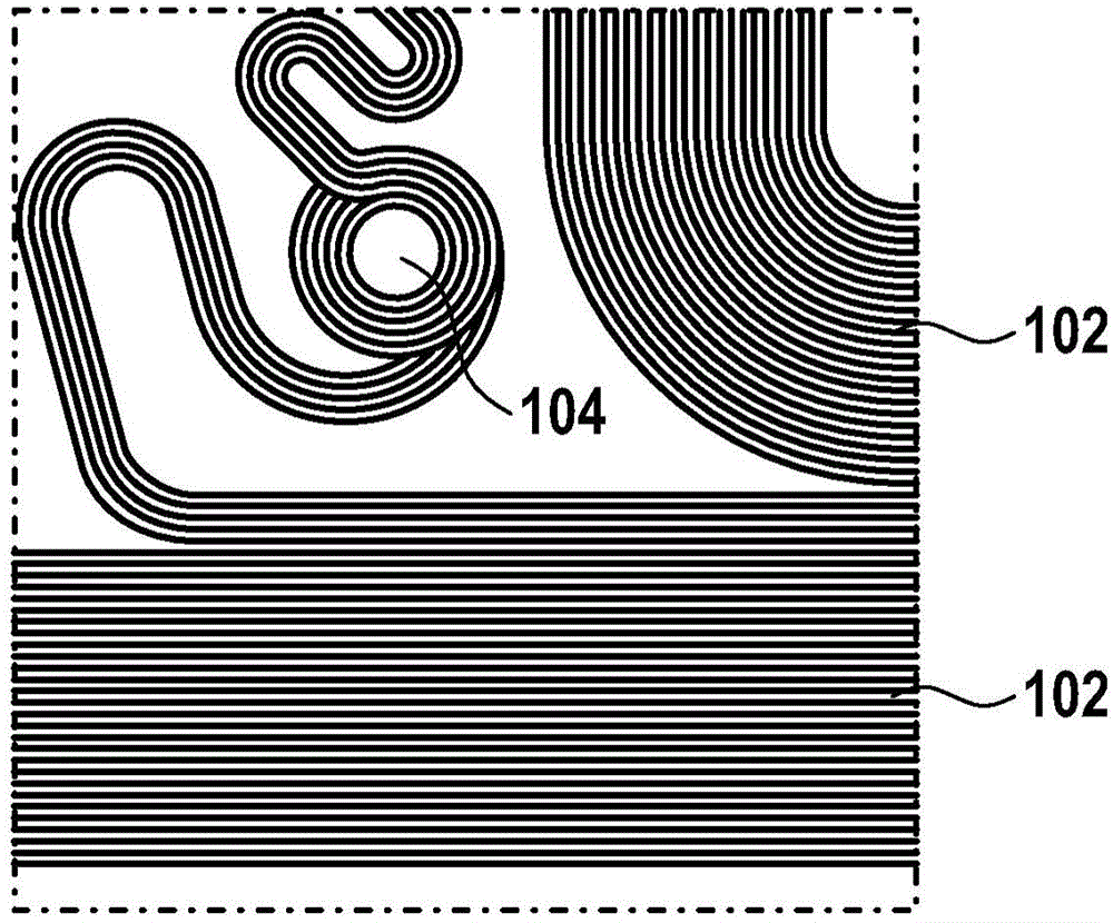
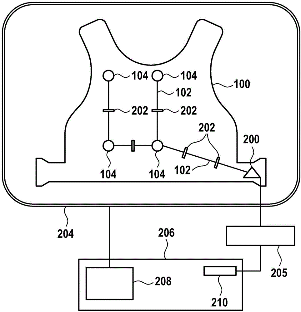
[0061] figure 2 A schematic diagram of the electrocardiogram sensor pad 100 is shown. The pad includes a plurality of electrodes 104 for collecting cardiac signals of the patient. Preferably, the sensor pad is attached to the patient, for example, worn by the patient. In this case, preferably, the sensor pad is a vest worn by the patient.

[0062] The individual electrode 104 is connected to the plug 200 of the vest 100. The connection is depicted by the wire 102. The wire 102 is segmented by a switch 202, wherein the switch can be switched between a closed state and an open state, wherein in the closed state, the electrode is electrically connected to the plug, and wherein, in the open state, the electrode is electrically isolated from the plug.

[0063] figure 2 The RF antenna 204 of the magnetic resonance imaging system is further shown in. Generally, such systems include superconducting...


PUM


Abstract

The invention relates to an electrocardiograph sensor mat (100), the mat (100) comprising a multitude of electrodes (104) for acquiring cardiac signals and a plug (200), wherein the electrodes (104) are connected to the plug (200) by electric wires (102), wherein the wires (102) are segmented by switches (202), wherein the switches (202) are switchable between a closed state and an open state, wherein in the closed state the electrodes (104) are electrically connected to the plug (200) and wherein in the open state the electrodes (104) are electrically isolated from the plug (200).

Description

Technical field [0001] The present invention relates to electrode cardiograph sensor pads. Background technique [0002] Heart disease is the number one cause of death in the world. The abnormal electrical activity of the heart due to, for example, arrhythmia including atrial fibrillation (AF) and ventricular tachycardia (VT), and congestive heart failure (CHF), is the fastest growing field of both clinical and industrial development. [0003] Electrocardiogram measurement (ECM) is a non-invasive technology that combines body surface electronic data collected from a large number of surface electrodes with detailed three-dimensional anatomical data obtained from, for example, computed tomography (CT), to provide an overview of the entire heart for each heartbeat. Detailed cardiac electrical activity information. Therefore, it is possible to deliver detailed electrophysiological information that could only be measured in invasive electrophysiological procedures using cardiac cathet...

Claims


Application Information

Patent Timeline
IPC IPC(8): A61B5/0408A61B5/055A61B5/296A61B5/308
CPCA61B5/6805A61B5/7203A61B2562/221A61B5/6892A61B5/04085A61B5/055A61B2562/222A61B2562/227A61B5/282
Inventor J·斯明克S·魏斯S·克吕格尔
Owner KONINKLJIJKE PHILIPS NV
Why Eureka
Try Eureka