ultrasonic sensor

A technology of ultrasonic sensors and acoustic converters, applied in the field of ultrasonic sensors

Active Publication Date: 2017-03-22
ROBERT BOSCH GMBH
View PDF2 Cites 0 Cited by
  • Summary
  • Abstract
  • Description
  • Claims
  • Application Information

AI Technical Summary

Problems solved by technology

There is thus the possibility of structure-borne sound being transmitted from the diaphragm via the filling material to the housing

Method used


Image

  • ultrasonic sensor

Examples


Embodiment Construction

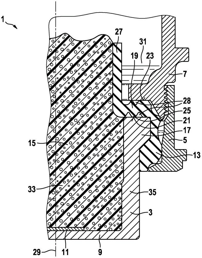
[0022] An ultrasonic sensor designed according to the invention is shown in the single figure.

[0023] The ultrasonic sensor 1 comprises a diaphragm pot 3 which is fastened to a housing 7 by means of a union nut 5 .

[0024] On the bottom 9 of the diaphragm pot 3 a sound transducer 11 is mounted on the inner side. Ultrasonic pulses are generated by means of the acoustic transducer 11 , which vibrate the bottom 9 of the diaphragm pot 3 . The vibrations are transmitted outwards, whereby sound pulses are emitted by the ultrasonic sensor 1 . In the presence of an object, the emitted sound pulse is reflected by said object and the echo is picked up by the bottom 9 of the diaphragm pot 3 . As a result, the bottom 9 of the diaphragm pot 3 is vibrated, which vibrations are transmitted to the sound transducer 11 . Thus, vibrations are detected by the acoustic transducer 11 and converted into a signal. In this way, the distance to the object can be determined via the acoustic propa...


PUM


Abstract

The invention relates to an ultrasound sensor for sending and / or receiving ultrasound signals, comprising a diaphragm cup (3) having a transducer (11) and a housing (7), wherein the diaphragm cup (3) is releasably connected to the housing (7), a decoupling ring (13) is accommodated between the membrane cup (3) and the housing (7), and the membrane cup (3) is filled with a filling material (15). The decoupling ring (13) comprises a lip (27) that is designed in such a way that a gap (31) is formed between the lip (27) and the housing inner wall and the filling material (15) is accommodated in a space at the decoupling ring (13), which space is enclosed by the membrane cup (3) and the lip (27). The invention further relates to a use of the ultrasound sensor.

Description

technical field [0001] The invention starts from an ultrasonic sensor for emitting and / or receiving ultrasonic signals, said ultrasonic sensor comprising a diaphragm pot and a housing, said diaphragm pot having an acoustic wave converter, wherein said diaphragm pot is connected to said The housing is detachably connected and a decoupling ring is accommodated between the diaphragm pot and the housing, and the diaphragm pot is filled with a filling material. Furthermore, the invention also relates to the use of ultrasonic sensors. Background technique [0002] Fields of use of ultrasonic sensors are, for example, driver assistance systems in motor vehicles. In the driver assistance system, the distance to objects surrounding the motor vehicle is determined by means of ultrasonic sensors. For this purpose, the ultrasonic sensor emits sound pulses which are reflected by objects in the surroundings of the motor vehicle. The echoes thus reflected are received and the distance t...

Claims


Application Information

Patent Timeline
Patent Type & Authority Patents(China)
IPC IPC(8): G10K9/122
CPCG10K9/22
Inventor D·巴尔特伊拉B·巴亚尔塞汉
Owner ROBERT BOSCH GMBH
Why Eureka
Try Eureka