Piezoelectric acoustic transducer

a technology of piezoelectric acoustic transducer and acoustic transducer, which is applied in the direction of electric transducers, deaf-aid sets, electrical equipment, etc., can solve the problem that the conventional piezoelectric acoustic transducer has less bass reproduction capability, and achieves the effect of improving power efficiency and high sound pressur

Active Publication Date: 2012-04-26
PANASONIC CORP
View PDF3 Cites 17 Cited by
  • Summary
  • Abstract
  • Description
  • Claims
  • Application Information

AI Technical Summary

Benefits of technology

[0023]According to the present invention described above, by coupling a plurality of piezoelectric diaphragms to one another in a thickness direction and causing bending deformations in opposite directions, a piezoelectric type loudspeaker which allows reproduction of a high sound pressure without increasing a voltage applied to a piezoelectric element can be provided. Also, according to the present invention, connection of electric resistance in series to a piezoelectric element mounted on a piezoelectric diaphragm that does not contribute to radiation of the sound wave, among the plurality of piezoelectric diaphragms, improves power efficiency in a high frequency band without providing a signal input circuit per diaphragm.

Problems solved by technology

This raises a problem that, as compared to electrodynamic loudspeakers having a diaphragm which has equivalent area, the conventional piezoelectric acoustic transducers have less bass reproduction capability.

Method used


Image

  • Piezoelectric acoustic transducer
  • Piezoelectric acoustic transducer
  • Piezoelectric acoustic transducer

Examples


first embodiment

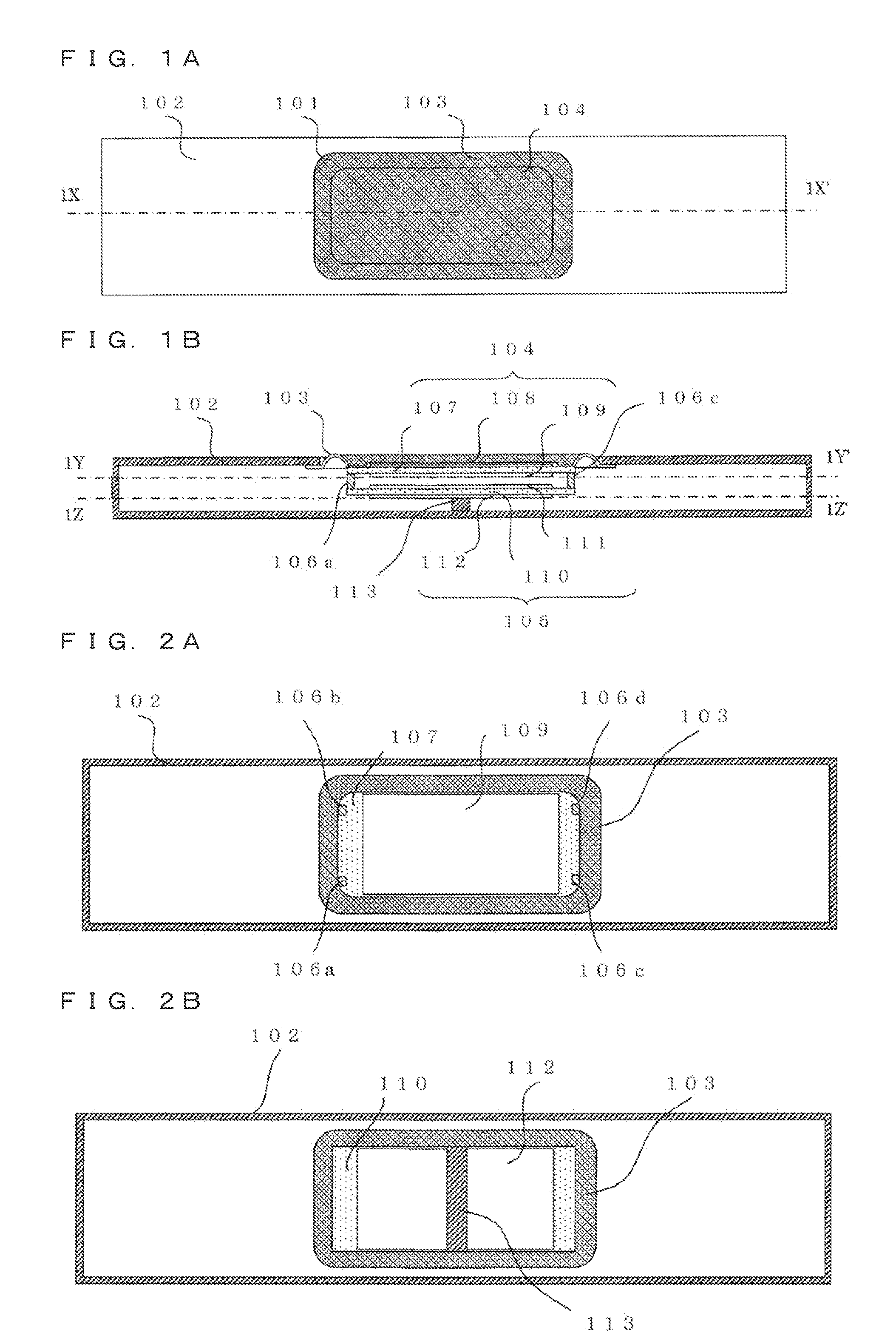
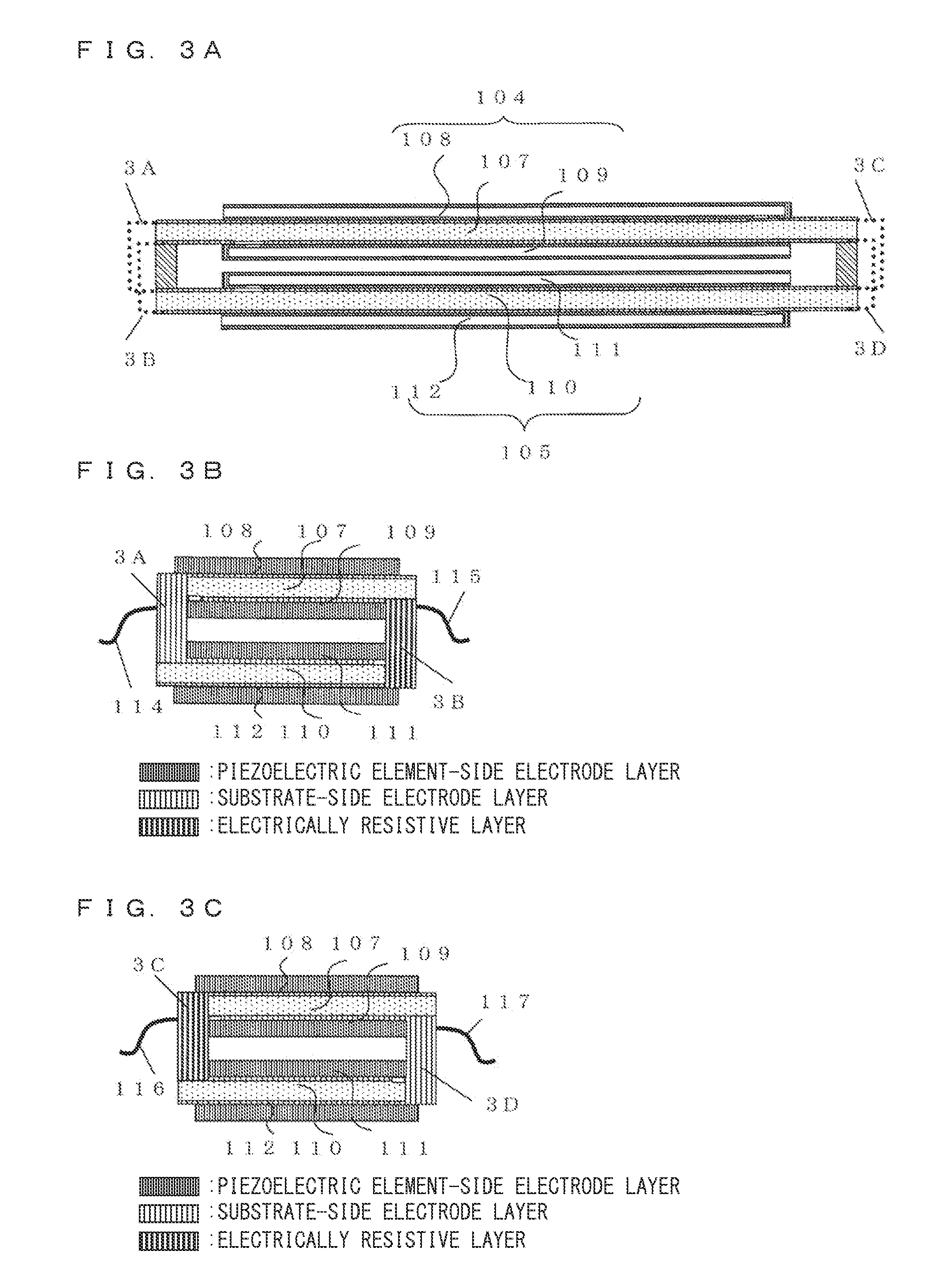
[0089]Referring to FIGS. 1A and 1B, a structure of a piezoelectric type loudspeaker 101 according to a first embodiment will be described. FIG. 1A is a top view of the piezoelectric type loudspeaker 101 according to the first embodiment. FIG. 1B is a sectional view taken from a plane parallel to a sound wave radiation direction in the piezoelectric type loudspeaker 101 shown in FIG. 1A. In FIG. 1A, of components of a housing 102 and the piezoelectric type loudspeaker 101, an upper surface of an upper piezoelectric diaphragm 104 is shown. Also, FIG. 1B shows a sectional view of the piezoelectric type loudspeaker 101 shown in FIG. 1A, taken along a line 1X-1X′.

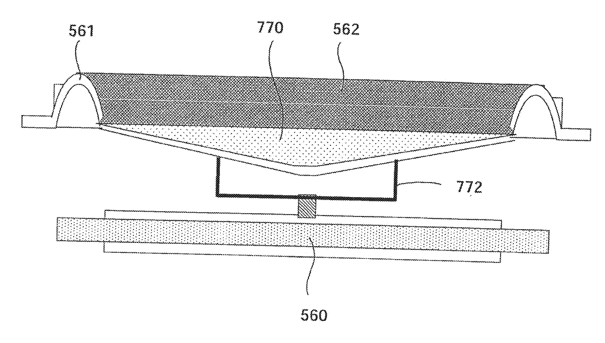
[0090]In FIG. 1B, the piezoelectric type loudspeaker 101 mainly includes the upper piezoelectric diaphragm 104, a lower piezoelectric diaphragm 105, coupling members 106a, 106b, 106c, and 106d, and an edge 103. The piezoelectric type loudspeaker 101 has a left-right symmetric structure about a centerline (not shown) of FIG. 1B. ...

second embodiment

[0106]A piezoelectric type loudspeaker 201 according to a second embodiment has characteristics in that the electric resistances are provided on a substrate surface at a fixing portion of the lower piezoelectric diaphragm in the first embodiment. Hereinafter, description centered on the characteristics will be given, and those in common with the piezoelectric type loudspeaker 101 according to the first embodiment are basically omitted.

[0107]Referring to FIGS. 7A and 7B, a structure of the piezoelectric type loudspeaker 201 according to the second embodiment will be described. FIG. 7A is a top view of the piezoelectric type loudspeaker 201 according to the second embodiment. FIG. 7B is a sectional view taken from a plane parallel to a sound wave radiation direction in the piezoelectric type loudspeaker 201 shown in FIG. 7A. FIG. 7B shows a sectional view of FIG. 7A taken along a line 2X-2X′. In FIG. 7B, the piezoelectric type loudspeaker 201 mainly includes a housing 202, an upper pi...

third embodiment

[0113]A piezoelectric type loudspeaker 301 according to a third embodiment has characteristics in that the lower piezoelectric diaphragm is not disposed facing the upper piezoelectric diaphragm, but disposed being shifted in a thickness direction from an extension plane of the upper piezoelectric diaphragm in the first embodiment. Hereinafter, description centered on the characteristics will be given, and those in common with the piezoelectric type loudspeaker 101 according to the first embodiment are basically omitted.

[0114]Referring to FIGS. 11A and 11B, a structure of the piezoelectric type loudspeaker according to the third embodiment will be described. FIG. 11A is a top view of the piezoelectric type loudspeaker 301 according to the third embodiment. FIG. 11B is a sectional view taken from a plane parallel to a sound wave radiation direction in the piezoelectric type loudspeaker 301 according to the third embodiment. In FIG. 11A, of components of a housing 302 and the piezoelec...


PUM


Abstract

Provided is a piezoelectric type loudspeaker capable of reproducing a high sound pressure in a limited space, without increasing a voltage applied to a piezoelectric element in a bass range. A plurality of piezoelectric diaphragms are disposed in parallel, and coupled to one another in a thickness direction of the diaphragms via a coupling member, and a polarity of the piezoelectric element and the applied voltage are defined so as to cause deformations in opposite directions from each other. One diaphragm includes an edge on a periphery, and operates as a sound wave radiation surface. At least one diaphragm is fixed to a housing side via a fixing member. Series resistance is connected to the piezoelectric element on the piezoelectric diaphragm fixed to the housing side.

Description

TECHNICAL FIELD[0001]The present invention relates to a piezoelectric acoustic transducer, and more particularly to a piezoelectric acoustic transducer which achieves both space-saving and enhancement of bass reproduction capability.BACKGROUND ART[0002]Conventional piezoelectric acoustic transducers (“piezoelectric type loudspeaker”) use natural resonance of a diaphragm and a bending deformation of the diaphragm, which uses the converse piezoelectric effect, to reproduce sounds. This raises a problem that, as compared to electrodynamic loudspeakers having a diaphragm which has equivalent area, the conventional piezoelectric acoustic transducers have less bass reproduction capability. As means which overcomes such problem, there are piezoelectric type loudspeakers which have an edge and damper formed between a frame and a diaphragm (e.g., see Patent Literature 1).[0003]FIG. 44 is an external view of a piezoelectric type loudspeaker disclosed in Patent Literature 1. A piezoelectric ty...

Claims


Application Information

Patent Timeline
Patent Type & Authority Applications(United States)
IPC IPC(8): H04R17/00
CPCH04R1/22H04R2499/11H04R17/00H04R7/18
Inventor FUJISE, AKIKO
Owner PANASONIC CORP
Why Eureka
Try Eureka