Noninvasively low-frequency ultrasonic apparatus for the brain therapy

a low-frequency ultrasonic and brain therapy technology, applied in the field of ultrasonic equipment, can solve the problems of inability to reach the work of inducing a larger area of bbb disruption, no more extensive applications, and high system cost, so as to reduce the shielding phenomenon caused by the skull's absorption of ultrasound, the effect of expanding the inducing area effectively and low cos

a low-frequency ultrasonic and brain therapy technology, applied in the field of ultrasonic equipment, can solve the problems of inability to reach the work of inducing a larger area of bbb disruption, no more extensive applications, and high system cost, so as to reduce the shielding phenomenon caused by the skull's absorption of ultrasound, the effect of expanding the inducing area effectively and low cos

US20100010394A1Inactive Publication Date: 2010-01-14CHANG GUNG UNIVERSITY

Image

  • Noninvasively low-frequency ultrasonic apparatus for the brain therapy
  • Noninvasively low-frequency ultrasonic apparatus for the brain therapy
  • Noninvasively low-frequency ultrasonic apparatus for the brain therapy

Examples


Embodiment Construction

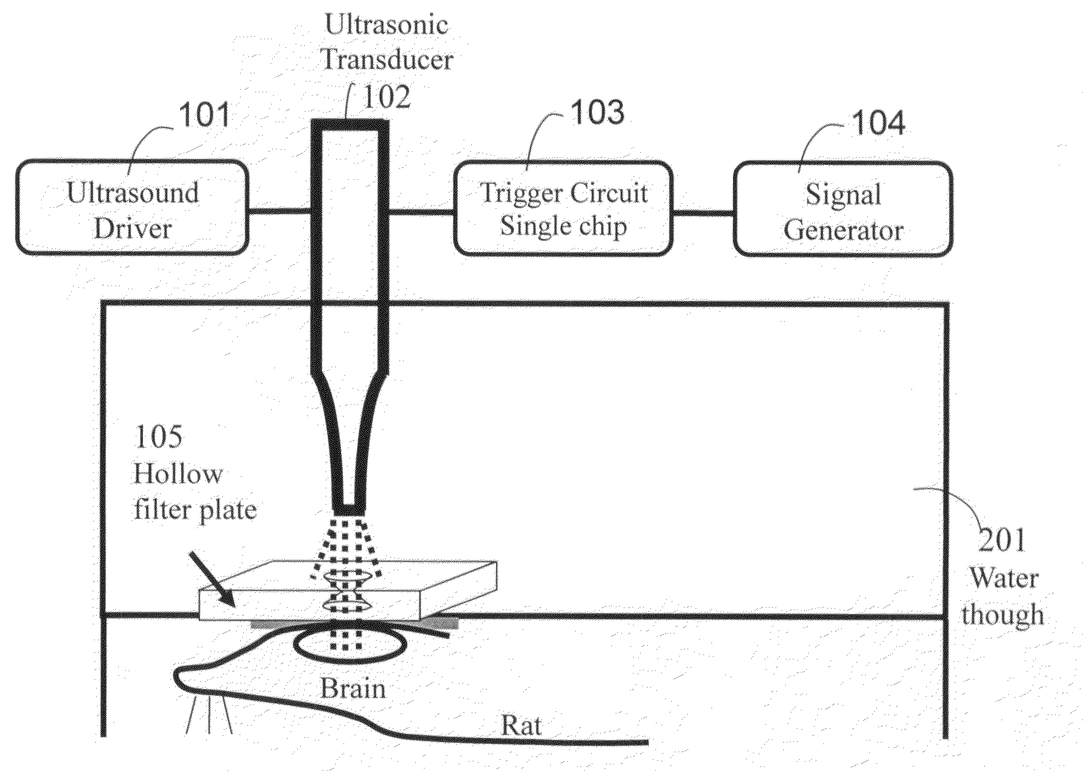
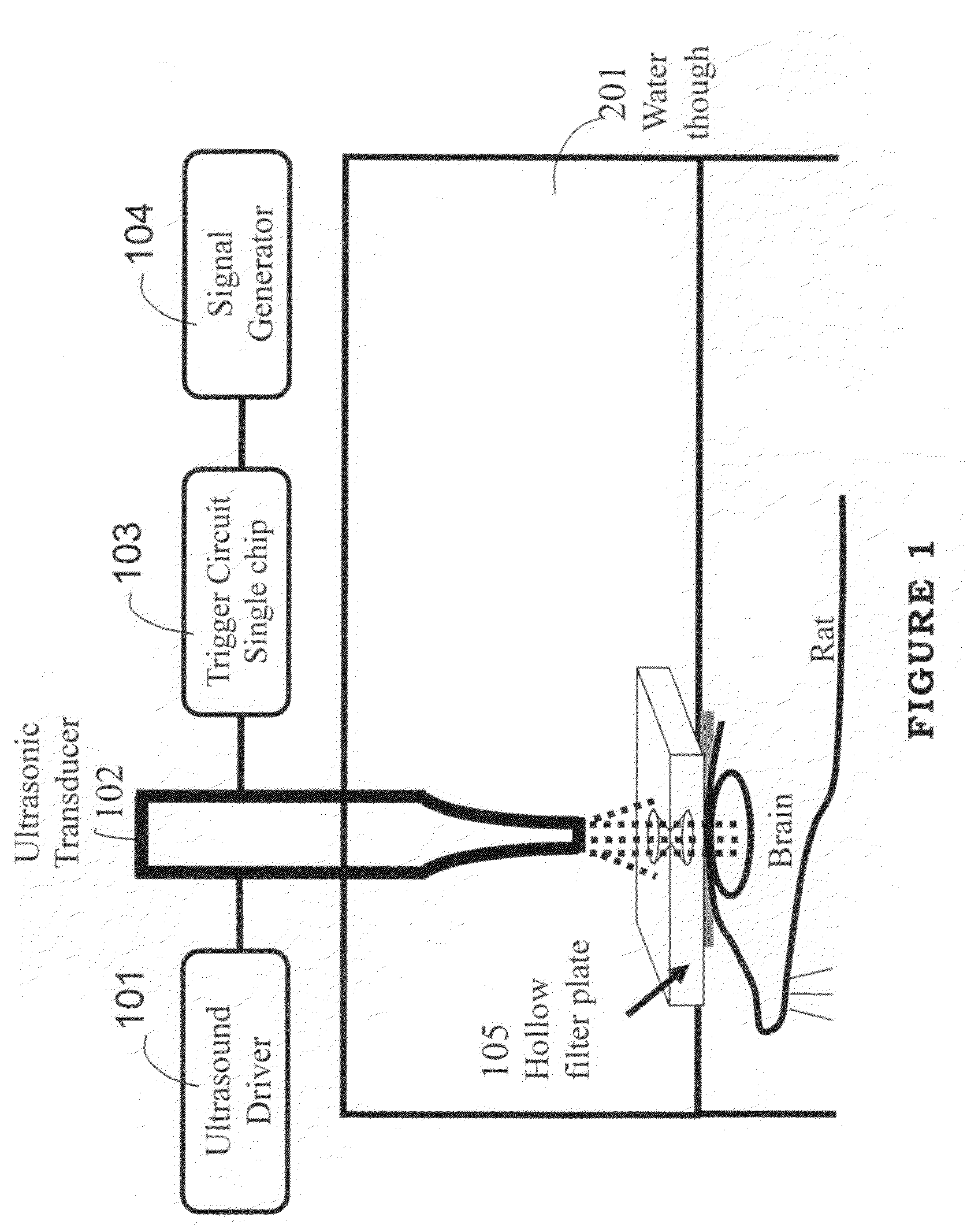
[0020]The invention relates to an ultrasonic apparatus having low-frequency spherical wave. As shown in FIG. 1, it comprises the ultrasound driver 101 has driving function, which can drive the ultrasonic transducer 102; the ultrasonic transducer 102, which can generate low-frequency ultrasound as 28 kHz. The trigger circuit single chip 103 has circuit control function. The signal generator 104 can generate sine burst signal, and the hollow filter plate 105 has ultrasound filtering function.

[0021]As shown in FIG. 1 again, the ultrasound driver 101 is connected to the ultrasonic transducer 102. The trigger circuit single chip 103 is connected to the signal generator 104 and the ultrasonic transducer 102. The hollow filter plate 105 is also called as the focusing device having filtering and focusing function for ultrasound. It is installed at the tip of the ultrasonic transducer 102, which is the low-frequency device of the invention.

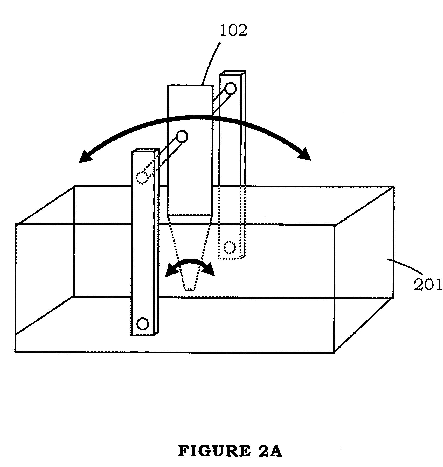
[0022]The invention must be installed in water troug...


PUM


Abstract

Ultrasonic energy has been proven that at suitable frequency range (670-kHz to 2-MHz), ultrasound can be focused to a specific target, and the concentrated energy has sufficient high acoustic pressure so that capable of inducing localized blood-brain barrier (BBB) disruption, which has an important implication on noninvasively delivering drug into brain.

Description

BACKGROUND OF THE INVENTION[0001]1. Field of the Invention[0002]The invention relates to an ultrasonic apparatus, particularly to an ultrasonic apparatus that can emit low-frequency spherical wave.[0003]2. Description of the Prior Art[0004]The conventional focusing-type ultrasonic apparatus can generate focused function by selecting suitable frequency range (670 kHz to 2 MHz). Meantime, the focused area has sufficient high acoustic pressure so that capable of inducing localized blood-brain barrier (BBB) disruption, which is an important implication on noninvasively delivering drug into brain. Although the conventional focusing-type ultrasonic apparatus can induce localized BBB disruption temporarily, yet they are still high-frequency ultrasonic systems. Thus the invasive way has to be used to induce BBB disruption, and it still is concentrated to a small area. It is unable to reach the work of inducing larger area of BBB disruption. Also, the cost of system is pretty high and there ...

Claims


Application Information

Patent Timeline
14 Jan 2010
Publication
US20100010394A1
IPC
A61N7/00
CPC
A61N7/00
Inventors
LIU, HAO-LI; HUANG, WEN-CHENG