Ultrasonic transducer

a transducer and ultrasonic technology, applied in the field of ultrasonic transducers, can solve the problems of insufficient absorption of unnecessary vibration, inability to detect ultrasonic waves reflected from obstacles, and inability to prevent leakage of piezoelectric energy obtained by piezoelectric elements, etc., to achieve excellent reverberation characteristics and high sound pressure

Active Publication Date: 2009-06-16
MURATA MFG CO LTD
View PDF11 Cites 19 Cited by
  • Summary
  • Abstract
  • Description
  • Claims
  • Application Information

AI Technical Summary

Benefits of technology

[0011]To overcome the problems described above, preferred embodiments of the present invention provide an ultrasonic transducer capable of radiating ultrasonic waves with a high sound pressure and having excellent reverberation characteristics.

Problems solved by technology

With this, electrical signals based on the vibration of the piezoelectric element generated by the ultrasonic waves reflected from an obstacle are mixed with the electrical signals generated by the vibration caused by the reverberation, and the ultrasonic waves reflected from the obstacle cannot be detected.
However, the unnecessary vibration cannot be sufficiently absorbed.
However, since the end portion of the outer case is not in contact with the directivity controller, the leakage of the vibrational energy obtained by the piezoelectric element cannot be prevented.
That is, a material with a high density has a high acoustic impedance, and such a material is not easily vibrated.
However, reverberation is still generated at the end portion of the outer case when the end portion of the outer case is not in contact with the inner case.

Method used


Image

  • Ultrasonic transducer
  • Ultrasonic transducer
  • Ultrasonic transducer

Examples


example 1

[0074]Ultrasonic transducers including cap members and inner frames as shown in FIGS. 3 and 4 were produced as Examples 1 and 2, respectively. Moreover, an ultrasonic transducer including an inner frame having the same shape as those shown in FIGS. 3 and 4 and having no through-holes was produced as a comparative example. The reverberation characteristics of these ultrasonic transducers were measured by applying a voltage of about 60 V to piezoelectric elements during a driving time of about 0.60 ms. The results of Example 1, Example 2, and the comparative example are shown in FIGS. 12 to 14, respectively. In FIGS. 12 to 14, the abscissa is divided into 0.2 ms sections.

[0075]The time periods from when the driving voltage was applied to when the reverberation was attenuated were about 0.78 ms, about 0.69 ms, and about 1.23 ms in Example 1, Example 2, and the comparative example, respectively. The results show that the reverberation characteristics were improved in the ultrasonic sens...


PUM


Abstract

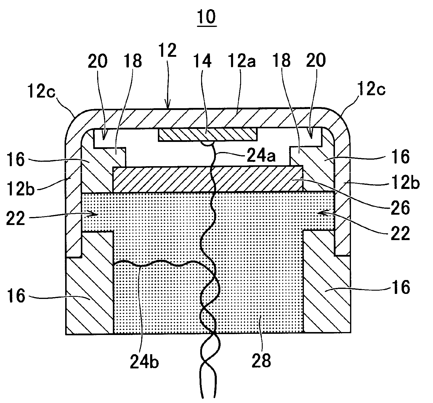
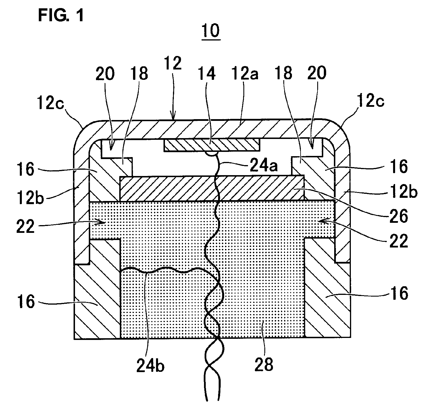
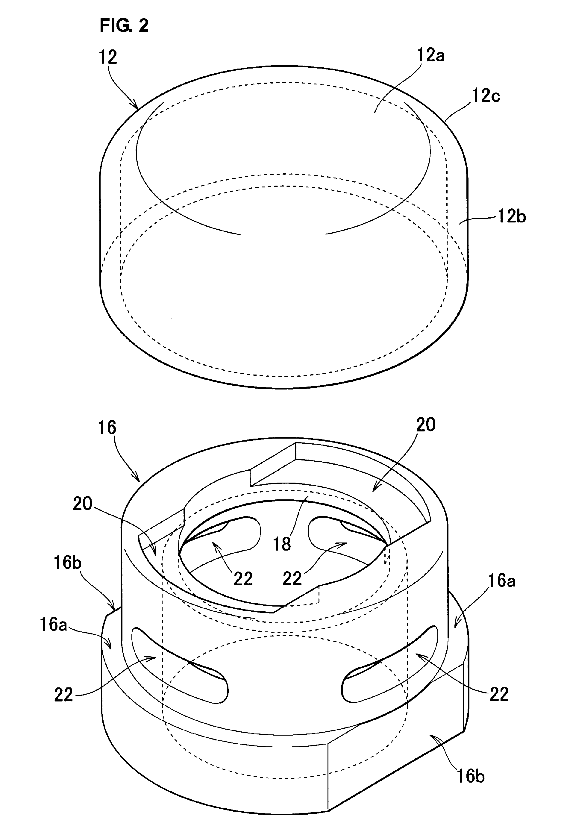
An ultrasonic transducer includes a cylindrical cap member having a bottom. A piezoelectric element is bonded to the inner side of a bottom portion of the cap member using a conductive adhesive or other suitable adhesive. An inner frame made of a material having an acoustic impedance greater than that of the cap member is fitted into the cap member so as to be in contact with a side portion, including the end portion, of the cap member. Through-holes are provided in the side portion of the inner frame. Lead wires are connected to the piezoelectric element and the inner frame, respectively. A sound absorber and a damper are inserted into the inner frame. The damper is in direct contact with the side portion of the cap member via the through-holes of the inner frame.

Description

BACKGROUND OF THE INVENTION[0001]1. Field of the Invention[0002]The present invention relates to ultrasonic transducers, and in particular, to ultrasonic transducers used as, for example, back-up sonar devices for automobiles.[0003]2. Description of the Related Art[0004]FIG. 15 illustrates an example of a known ultrasonic transducer. An ultrasonic transducer 1 includes a cylindrical outer case 2 with a bottom. A piezoelectric element 3 is disposed on the inner bottom surface of the outer case 2. Furthermore, a cylindrical directivity controller 4 is disposed inside the outer case 2. As shown in FIG. 16, the directivity controller 4 has thick portions and thin portions formed by, for example, a hexagonal through-hole. This directivity controller 4 is fitted into the outer case 2 so as to be in contact with the side surface and the bottom surface of the outer case 2. A back plate 5 is fitted into the outer case 2 at a position adjacent to the opening of the outer case 2, and the end p...

Claims


Application Information

Patent Timeline
Patent Type & Authority Patents(United States)
IPC IPC(8): H01L41/08H04R1/20H04R17/00
CPCG10K9/122G10K9/22G01S7/521G01S2013/9389G01S15/931G01S2015/938B06B1/06H04R1/32H04R17/02H04R2499/13G01S2013/93275
Inventor ASADA, TAKAAKISHIMAMOTO, TAKAYUKIMURATA, KOJIFURUYA, MIO
Owner MURATA MFG CO LTD
Why Eureka
Try Eureka