
Soldering iron

A soldering iron, cutting-edge technology, applied in the direction of soldering irons, soldering stations, auxiliary devices, etc., can solve the problems of reduced efficiency of current flow, secondary battery safety problems, etc., and achieve the effect of reducing soldering operations

Inactive Publication Date: 2014-09-17
SAMSUNG SDI CO LTD
View PDF7 Cites 0 Cited by
  • Summary
  • Abstract
  • Description
  • Claims
  • Application Information

AI Technical Summary

Problems solved by technology

In this case, poor contact of electronic components, etc. interrupts the flow of current in the secondary battery and lowers the efficiency
In severe cases, the safety of the secondary battery will be a problem due to the non-operation of the secondary protection device

Method used


Image

  • Soldering iron
  • Soldering iron
  • Soldering iron

Examples


Embodiment Construction

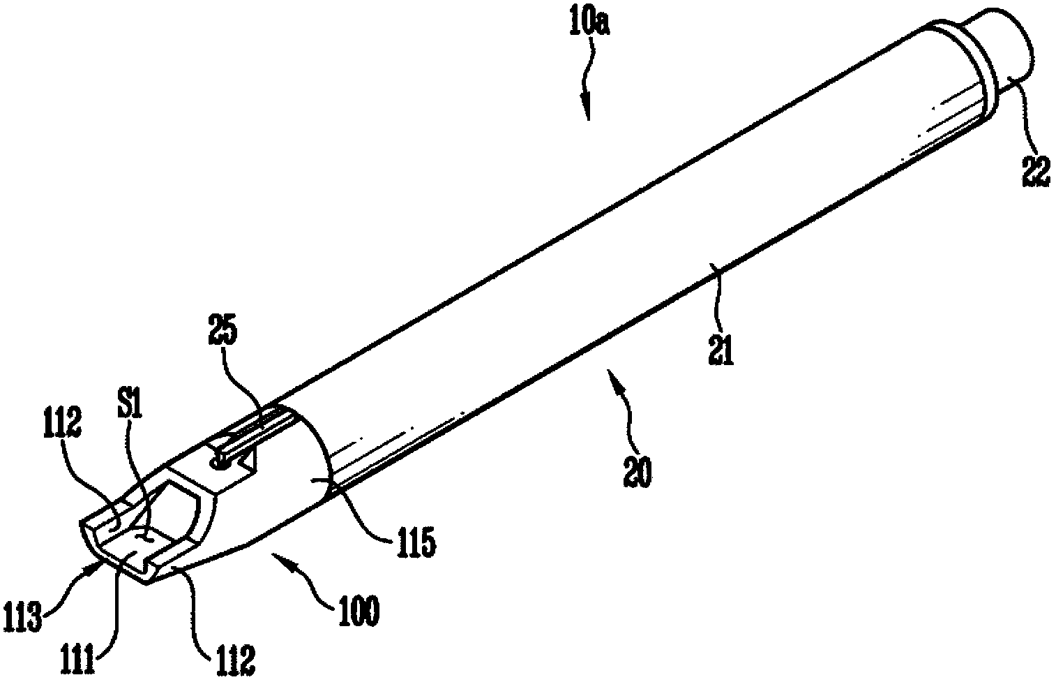
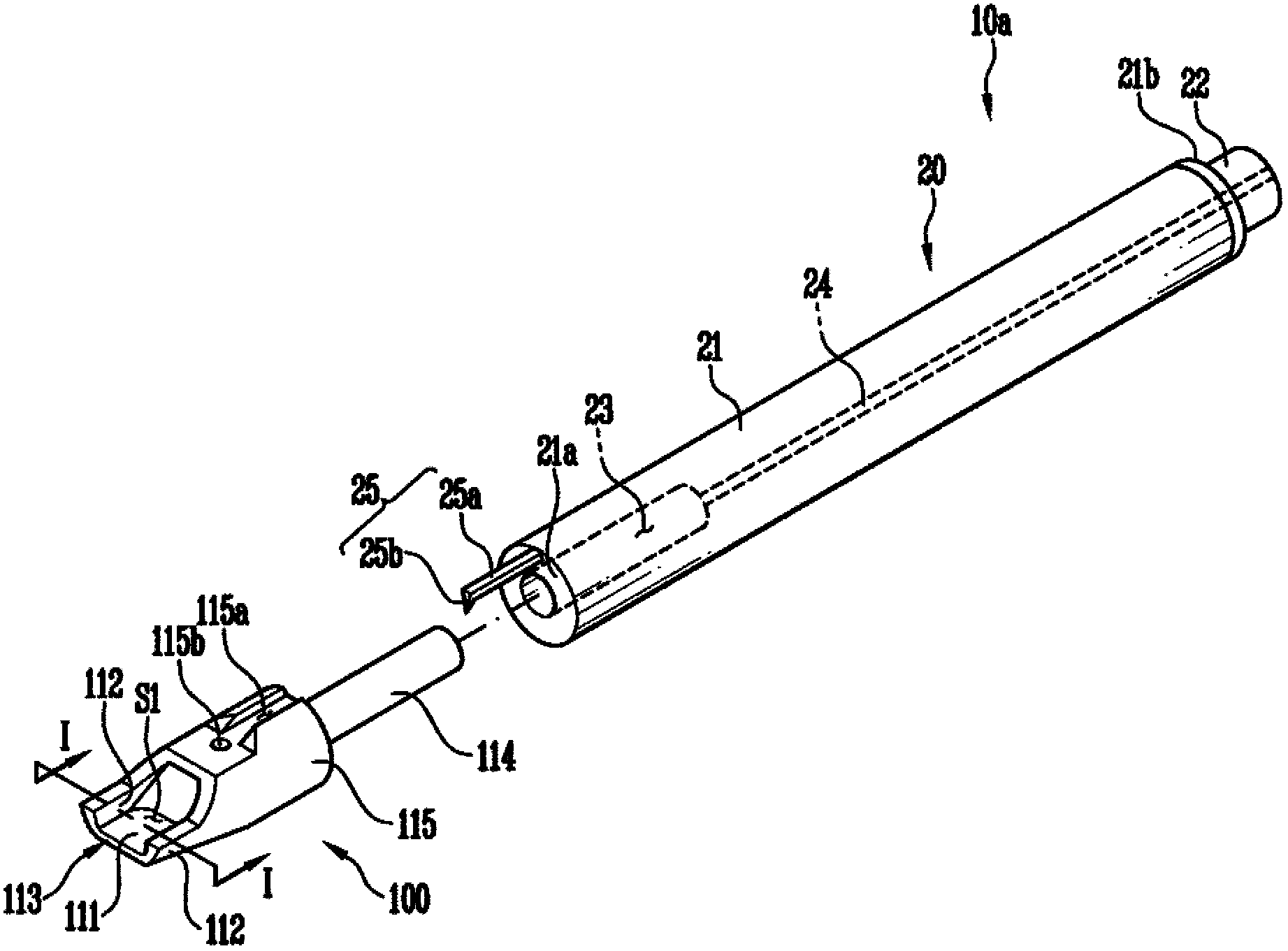
[0036] figure 1 is a perspective view of a soldering iron according to an embodiment of the present invention. figure 2 for figure 1 exploded perspective view of a soldering iron.

[0037] The soldering iron 10a according to this embodiment is used when components are soldered to the board. The soldering iron 10 a may include a tip portion 100 that melts lead and has a bent portion that contacts the lead, and a tip fixing portion 20 that has a heater that heats the tip portion 100 .

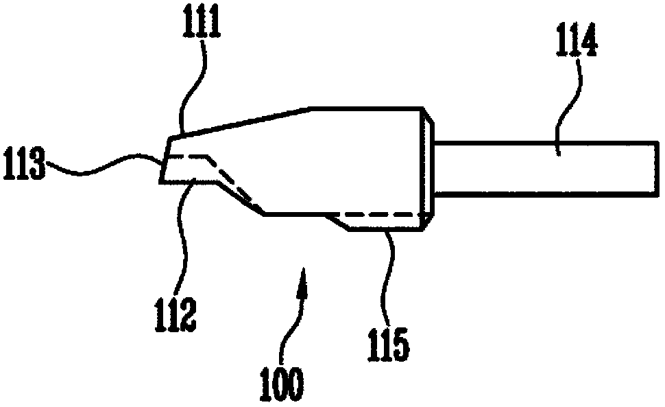
[0038] The tip portion 100 is a portion that melts lead by direct contact with lead. The tip part 100 may include a base 111 in direct contact with the lead, side parts 112 bent at one end and the other end of the base 111, respectively, a support part 115 connected to the upper part of the side part 112 and the base 111, and a tip from the support part 115 toward the tip. The extension 114 protrudes from the fixing part 20 . The base part 111 , the support part 115 and the extension part 1...


PUM


Abstract

Soldering iron used for soldering elements on a plate comprises a tip end part and a tip end fixing part. The tip end part melts lead and is provided with a bended part for contacting lead. The tip end fixing part is provided with a heater for heating the tip end part.

Description

technical field [0001] Aspects of the invention relate to soldering irons. Background technique [0002] In general, a secondary battery is a battery capable of being charged and discharged many times, and demand for a secondary battery suitable for a power source of portable devices has recently increased with the development of electric, electronic, communication, and computer industries. Research on the secondary battery has been conducted in various fields in order to improve performance and safety as its form and number increase. [0003] A circuit board is provided to the secondary battery to control the flow of current, and a plurality of electronic components such as secondary protection devices are mounted on the circuit board. In this case, poor contact of electronic components or the like interrupts the flow of current in the secondary battery and reduces efficiency. In severe cases, the safety of the secondary battery may be problematic due to non-operation of ...

Claims


Application Information

Patent Timeline
IPC IPC(8): B23K3/03
CPCB23K3/025B23K3/0338B23K3/027B23K3/0369B23K3/08
Inventor 金基雄崔宰熏
Owner SAMSUNG SDI CO LTD
Learn More