
Transmission line thunder leading width calculating method based on actually measured lightning stroke data

A technology of transmission lines and calculation methods, which is applied in the directions of calculation, electrical digital data processing, and special data processing applications, etc., and can solve the problem of large differences in lightning induction capabilities, difficulty in meeting the needs of differentiated lightning protection performance evaluation, and different lightning induction capabilities. And other issues

Active Publication Date: 2014-09-17
HAINAN POWER GRID CO LTD ELECTRIC POWER RES INST +1
View PDF3 Cites 7 Cited by
  • Summary
  • Abstract
  • Description
  • Claims
  • Application Information

AI Technical Summary

Problems solved by technology

In recent years, with the in-depth research on lightning physics and long air gap discharge theory, the lightning induction capacity of transmission lines is not only related to the height of towers and the spacing of lightning protection lines, but also related to factors such as topography and line structure; actual operation experience shows that, Different terrains and landforms often have different lightning induction capabilities, especially in mountainous areas and plains. The empirical formula of lightning induction width is becoming more and more difficult to meet the actual needs of the project.
[0003] The traditional empirical calculation formula derived from the operating experience of typical low-voltage lines has been difficult to meet the needs of differential lightning protection performance evaluation, and it is urgent to propose a calculation method for the lightning induced width of transmission lines that can better reflect the actual situation

Method used


Image

  • Transmission line thunder leading width calculating method based on actually measured lightning stroke data
  • Transmission line thunder leading width calculating method based on actually measured lightning stroke data

Examples


Embodiment Construction

[0012] In order to better understand a method for calculating the lightning induced width of a transmission line based on the actual lightning strike data of the present invention, further description will be made in conjunction with relevant diagrams.

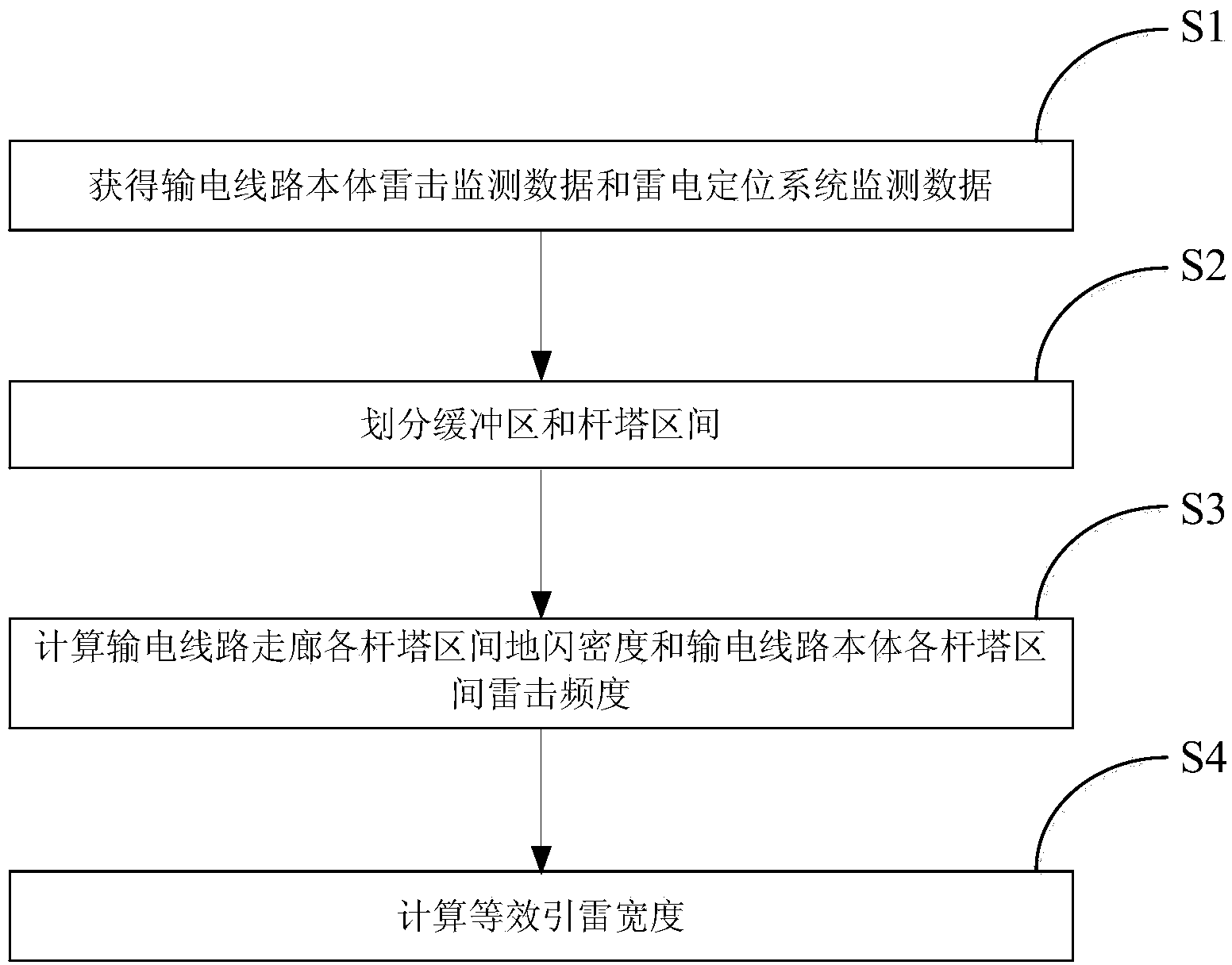
[0013] figure 1 It is a preferred flow chart of the method for calculating the width of a transmission line induced lightning based on actually measured lightning strike data in the present invention.

[0014] First, step S1 is implemented to obtain the lightning strike monitoring data of the transmission line body and the lightning location system monitoring data.

[0015] When implementing this step, traveling wave monitoring devices need to be installed distributedly on the transmission line to obtain the lightning strike monitoring data of the transmission line itself. Install a monitoring device in each phase, use the Rogowski coil to collect high-frequency traveling wave current waveform data, use the traveling wave cur...


PUM


Abstract

The invention relates to a transmission line thunder leading width calculating method based on actually measured lightning stroke data. The transmission line thunder leading width is calculated according to actually measured transmission line body lightning stroke data and thunder positioning system monitoring data. The method mainly comprises the following steps that firstly, the lightning stroke frequency and the cloud-to-ground lightning density of a transmission line body are obtained according to the transmission line body lightning stroke data and the thunder positioning system monitoring data, and secondly, the equivalent thunder leading width is calculated, wherein the computational formula of the equivalent thunder leading width is shown as d=f / rho, and d, f and rho represent the equivalent thunder leading width, the transmission line body lightning stroke frequency and the cloud-to-ground lightning density respectively. In the actual engineering application, compared with an existing method for obtaining the thunder leading width based on the empirical formula, the method has the advantage that the thunder leading width calculated based on the actually measured lightning stroke data is more reliable and accurate.

Description

technical field [0001] The method of the invention relates to the technical field of lightning protection for transmission lines, in particular to a method for calculating the lightning-induced width of a transmission line based on actually measured lightning strike data. Background technique [0002] The lightning induced width of the transmission line is one of the key parameters of the lightning protection performance evaluation model. In the traditional evaluation model, the lightning width is calculated using an empirical formula, which is equal to the sum of four times the height of the tower and the distance between the lightning conductors. In recent years, with the in-depth research on lightning physics and long air gap discharge theory, the lightning induction capacity of transmission lines is not only related to the height of towers and the spacing of lightning protection lines, but also related to factors such as topography and line structure; actual operation ex...

Claims


Application Information

Patent Timeline
IPC IPC(8): G06F19/00
Inventor 吴清钱冠军梁亚峰黄松谢施君陈钦柱窦宪鹤
Owner HAINAN POWER GRID CO LTD ELECTRIC POWER RES INST
Learn More