A thickness detection device

A thickness detection and thickness sensor technology, applied in the electronic field, can solve the problems that the thickness sensor cannot detect abnormalities, detection blind spots, etc.

Active Publication Date: 2017-04-26
GRG BAKING EQUIP CO LTD
View PDF5 Cites 0 Cited by
  • Summary
  • Abstract
  • Description
  • Claims
  • Application Information

AI Technical Summary

Problems solved by technology

[0004] However, it is measured by the thickness sensors arranged in a row. Since the thickness sensors are too close to each other, there will be mutual interference, so a certain gap should be reserved between each thickness sensor. In passing, these thickness sensors cannot detect abnormalities, resulting in detection blind spots

Method used


Image

  • A thickness detection device
  • A thickness detection device
  • A thickness detection device

Examples


Embodiment Construction

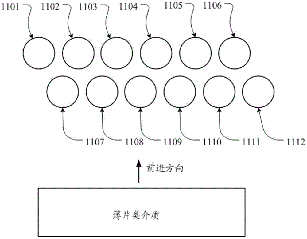
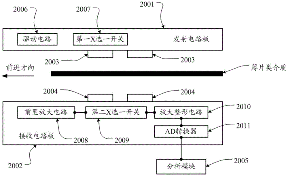
[0052] An embodiment of the present invention provides a thickness detection device, which is used to prevent abnormal features such as foreign objects and damaged holes from passing through the gap, so that the thickness detection device does not have detection blind spots.

[0053] In order to make the purpose, features and advantages of the present invention more obvious and understandable, the technical solutions in the embodiments of the present invention will be clearly and completely described below in conjunction with the accompanying drawings in the embodiments of the present invention. Obviously, the following The described embodiments are only some, not all, embodiments of the present invention. Based on the embodiments of the present invention, all other embodiments obtained by persons of ordinary skill in the art without making creative efforts belong to the protection scope of the present invention.

[0054] see figure 1 , an embodiment of a thickness detection ...


PUM


Abstract

The embodiment of the present invention discloses a thickness detection device, which is used to prevent abnormal features such as foreign objects and damaged holes from passing through the gap, so that the thickness detection device does not have a detection blind zone. A thickness detection device in an embodiment of the present invention includes: a plurality of thickness sensors divided into two rows in the forward direction of the sheet medium, with staggered distribution between the two rows, so that any point on the sheet medium is in the Passing through the sensing coverage of the thickness sensor in the forward direction.

Description

technical field [0001] The invention relates to the field of electronics, in particular to a thickness detection device. Background technique [0002] With the diversification of people's lives, the thickness detection of sheet media has gradually begun to be applied, and the application fields are becoming wider and wider. For example, ATM machines or banknote sorting machines in the commercial field need to detect the thickness of banknotes, so as to identify whether the banknotes are damaged, pasted with foreign objects, torn, etc., and can also use the thickness of banknotes as a standard for distinguishing authenticity. one. [0003] At present, the general method for detecting the thickness of sheet media is to combine the signals detected by multiple independent thickness sensors arranged in a row into the thickness characteristics of the entire banknote, so as to identify whether the banknote is abnormal. [0004] However, it is measured by the thickness sensors ar...

Claims


Application Information

Patent Timeline
Patent Type & Authority Patents(China)
IPC IPC(8): G07D5/02
CPCG07D5/02G07D7/08G07D7/16G07D7/164G01B17/02G01N29/041G01N29/4445G01N2291/0237G01N2291/0289
Inventor 黎明黄晓群
Owner GRG BAKING EQUIP CO LTD
Why Eureka
Try Eureka