Signal reconstruction method for sparse signals in frequency domain

A sparse signal and signal reconstruction technology, applied in the field of signal processing, can solve problems such as low efficiency, large data storage space, and high power consumption

Active Publication Date: 2017-03-22
HARBIN INST OF TECH
View PDF6 Cites 0 Cited by
  • Summary
  • Abstract
  • Description
  • Claims
  • Application Information

AI Technical Summary

Problems solved by technology

[0026] The purpose of the present invention is to propose a frequency-domain sparse signal reconstruction method based on a fast sensing matrix, to solve the problem that the existing method has a large amount of calculation, takes a long time, requires a large data storage space, consumes a large amount of power, and has low real-time performance , the problem of low efficiency

Method used


Image

  • Signal reconstruction method for sparse signals in frequency domain
  • Signal reconstruction method for sparse signals in frequency domain
  • Signal reconstruction method for sparse signals in frequency domain

Examples


specific Embodiment approach 1

[0079]Specific implementation mode 1: step 1 described in this implementation mode, use the analog-to-digital converter to collect the output signal of the filter, and obtain a series of sampling values, which are recorded as y(m), (m=1, 2,..., M), according to the generation mode of the MLS sequence itself and the output sampling rate fs, calculate a series of values ​​of the MLS sequence input to the multiplier within the sampling time t, denoted as p(n), (n=1,2,.. .,N),

[0080] Step 2: Input a 1V DC signal to one input terminal of the multiplier, and input a rectangular pulse signal to the other input terminal. The low level of the signal is 0V, the high level is 1V, and the high level duration is 0.1ms; and At the same time, use an analog-to-digital converter to collect the output signal of the low-pass filter, the sampling rate and sampling time are the same as fs and t in step 1, and the collected result is the impulse response of the multiplier and the low-pass filter,...

specific Embodiment approach 2

[0126] Specific embodiment two: the difference between this embodiment and specific embodiment one is: the acquisition process of y(m) in step one is:

[0127] The signal to be tested is input to one input terminal of the multiplier, and the other input terminal of the multiplier is used to input the MLS sequence; the output terminal of the multiplier is connected to the input terminal of the low-pass filter, and the output terminal of the low-pass filter is connected to the analog-to-digital conversion The input terminal of the converter is connected, and the output terminal of the analog-to-digital converter is connected with the input terminal of the host computer;

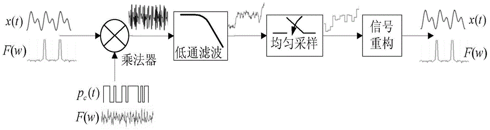
[0128] Input a measured analog signal x(t) and a MLS sequence p(t) into the multiplier for multiplication, the multiplied signal is filtered by a low-pass filter, and the filtered signal is sampled by an analog-to-digital converter. The sampling rate used during sampling is fc, the sampling time is t, and a ser...

specific Embodiment approach 3

[0129] Specific embodiment three: the difference between this embodiment and specific embodiment one or two is: the acquisition process of p(n) in step one is:

[0130]The MLS sequence is a series of values ​​calculated according to the set mode, and then output these values ​​one by one at the set sampling rate fs with the help of an arbitrary waveform generator to form an MLS sequence. Known, so all the values ​​of the MLS sequence within the sampling time t can be calculated, denoted as p(n), (n=1,2,...,N), N=fs×t;

[0131] The output sampling rate fs of the MLS sequence and the sampling rate fc used by the sampling filter output signal have the following relationship: fs=C×fc, and naturally have the following relationship N=C×M, C is an integer. to combine Figure 3 to Figure 6 This embodiment mode is explained. Other steps and parameters are the same as those in Embodiment 1 or Embodiment 2.


PUM


Abstract

The invention belongs to the technical field of signal processing, and relates to a signal reconstruction method for frequency domain sparse signals. The signal reconstruction method aims to solve the problems that in an existing method, the calculation amount is large, a long time is consumed, a large data memory space is needed, the power consumption is large, the real-time performance is poor and the efficiency is low. According to the signal reconstruction method, based on the symmetry of a discrete Fourier transformation matrix and some characteristics of matrix operation, the method of calculating a sensing matrix in a compressed sensing model is improved, a new method of calculating the sensing matrix is designed and then introduced into fast Fourier transformation, and therefore the calculation amount is decreased and the speed is increased. The signal reconstruction method can be applied to the field of signal processing.

Description

technical field [0001] The invention relates to an FFT-based compression matrix construction method, in particular to a signal reconstruction method for sparse signals in the frequency domain, and belongs to the technical field of signal processing. Background technique [0002] The traditional information acquisition and processing process must follow the Nyquist sampling theorem, that is, the sampling rate must be at least twice the highest frequency of the original signal, so that the original signal can be recovered from the discrete signal obtained by sampling without distortion. However, with the development of information technology, the disadvantages of this information acquisition and processing mode based on Nyquist sampling theorem are gradually exposed. For example, the sampling rate and processing speed of the front-end ADC are required to be high, the amount of sampled data is large, and the redundancy is high. [0003] The Compressed Sensing (CS) theory that ...

Claims


Application Information

Patent Timeline
Patent Type & Authority Patents(China)
IPC IPC(8): H03M7/30
Inventor 付宁张京超宋平凡乔立岩
Owner HARBIN INST OF TECH
Why Eureka
Try Eureka