Inverse visual area correcting method and device

A technology of inverse viewing area and viewpoint, which is applied in image communication, stereo system, electrical components, etc., and can solve the problem of image blurring in inverse viewing area.

Inactive Publication Date: 2014-09-17
HISENSE VISUAL TECH CO LTD
View PDF3 Cites 8 Cited by
  • Summary
  • Abstract
  • Description
  • Claims
  • Application Information

AI Technical Summary

Problems solved by technology

However, the method of adjusting the parallax of the inverse view zone only by adjusting the horizontal relative distance between viewpoints will still lead to blurred images in the inverse view zone.

Method used


Image

  • Inverse visual area correcting method and device
  • Inverse visual area correcting method and device
  • Inverse visual area correcting method and device

Examples


Embodiment Construction

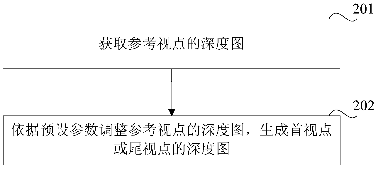
[0050] Embodiments of the present invention provide a reverse viewing zone correction method and device, which can obtain the depth map of the reference viewpoint; adjust the depth map of the reference viewpoint according to preset parameters, and generate the depth map of the first viewpoint or the last viewpoint; wherein, the first viewpoint and the last viewpoint The maximum grayscale value of the depth map should be smaller than the maximum grayscale value of other viewpoint depth maps within one cycle; the difference between the maximum grayscale values ​​of the depth maps of the first viewpoint and the last viewpoint is smaller than the first threshold. Since the maximum gray value of the depth map of the first view and the end view should be smaller than the maximum gray value of the depth maps of other viewpoints in a cycle, and the difference between the maximum gray value of the depth map of the first view and the end view is less than The first threshold, so as to en...


PUM


Abstract

The invention relates to the technical field of image display in a video system, in particular to an inverse visual area correcting method and device. The inverse visual area correcting method and device are used for solving the problem that blurring of an image in an inverse visual area can still be caused when the parallax of the inverse visual area is adjusted simply by adjusting the horizontal relative distance between viewpoints. The method comprises the steps of acquiring the depth map of a reference viewpoint; adjusting the depth map of the reference viewpoint according to preset parameters to generate the depth maps of an initial viewpoint and a tail viewpoint, wherein the maximum grey value of the depth map of the initial viewpoint and the maximum grey value of the depth map of the tail viewpoint should be smaller than the maximum grey values of the depth maps of other viewpoints in the same period, and the difference value between the maximum grey value of the depth map of the initial viewpoint and the maximum grey value of the depth map of the tail viewpoint is smaller than a first threshold. In this way, blurring of images in the inverse visual area is reduced, and the 3D display effect is improved.

Description

technical field [0001] The invention relates to the technical field of image display in a video system, in particular to a reverse viewing zone correction method and device. Background technique [0002] At present, naked-eye viewing of 3D is becoming a research hotspot because users do not need to wear corresponding equipment. [0003] Since there is a distance of about 8 cm between the two eyes of a person, when viewing an object, the left and right eyes see two images with a certain parallax. feel. Naked-eye 3D uses the principle of binocular offset to send two images with parallax to the left and right eyes of people independently, so that users can watch stereoscopic images with naked eyes. [0004] Taking the arrangement of 4 viewpoints as an example, viewpoints 1 to 4 are arranged circularly in the order of 1, 2, 3, 4, 1, 2, 3, 4... on the LCD screen, and the human eye can simultaneously receive a certain parallax between two adjacent viewpoints. The images are the...

Claims


Application Information

Patent Timeline
Patent Type & Authority Applications(China)
IPC IPC(8): H04N13/00
Inventor 高语函
Owner HISENSE VISUAL TECH CO LTD
Why Eureka
Try Eureka