

Shower head switch water outlet mechanism
A switch-out and shower technology, applied in the direction of spraying devices, spraying devices, etc., can solve the problems of unfavorable assembly and maintenance, old-fashioned transmission mode, lack of novelty, etc., and achieve novel structure, stable and reliable transmission, and easy processing and installation Effect
- Summary
- Abstract
- Description
- Claims
- Application Information
AI Technical Summary
Problems solved by technology
Method used
Image

Examples
Embodiment Construction
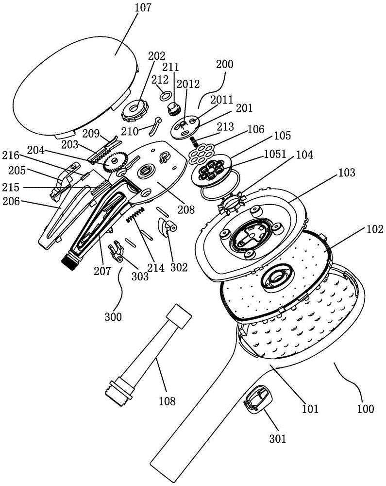
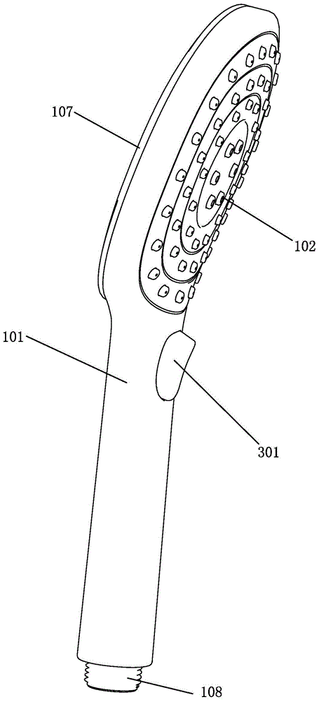
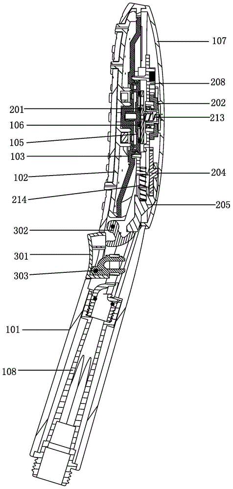
[0029] Examples, see Figure 1-Figure 6 As shown, a shower switch water outlet mechanism of the present invention includes a shower body 100, which has a water inlet and at least two water outlet functions; include:
[0030] Rotate the runner installed in the shower body 100, the water diversion plate 201 coaxially linked with the runner, the push rod 205 movably installed in the shower body 100, the gear 204 rotatably installed in the push rod 205, along the push rod The first rack 215 set in the direction of movement of 205, the second rack 203 movably installed in the shower body 100, and the gear 204 meshes with the first rack 215 to move along the first rack 215 under the action of the push rod 205. movement; the second rack 203 meshes with the gear 204, and one end thereof stretches toward the runner, and when the gear 204 advances along the first rack 215, it is moved towards the direction of the runner by the action of the gear 204 and pushes the runner to rotate, Th...
PUM
 Abstract
Description
Claims
Application Information