Annular air-locking flow-aiding device

An air-locking and ring-shaped technology, which is applied in transportation and packaging, conveying bulk materials, conveyors, etc., can solve the problems of small investment and output, poor air-locking effect, and difficulty in achieving the air-locking effect, and achieves a simple structure Compact, good air lock effect

Inactive Publication Date: 2014-09-24
HEFEI GOODTIMES AUTOMATION
View PDF7 Cites 2 Cited by
  • Summary
  • Abstract
  • Description
  • Claims
  • Application Information

AI Technical Summary

Problems solved by technology

[0002] In the pneumatic conveying of powdery materials, air lock devices are usually used. Currently known air lock devices include air lock pumps (screw pumps), air lock valves and other equipment. Larger, when the flow rate is greater than 3t / h (taking coal powder as an example), the air lock effect is ideal, and the investment and output are more cost-effective; but when the flow rate is less than 3t / h (taking coal powder as an example), the traditional Air-locking equipment, the effect of air-locking is poor, and the investment and output are relatively small
[0003] At present, the air-locking equipment for small-flow powder transportation is generally made of injection pipes based on the principle of Venturi tubes. Due to the different lengths and thicknesses of pipes on industrial sites, the number and size of elbows, and the pressure loss of conveying pipes, there are many factors. , it is difficult to achieve the ideal wind-locking effect in field use

Method used


Image

  • Annular air-locking flow-aiding device

Examples


Embodiment Construction

[0013] In order to make the technical means, creative features, goals and effects achieved by the present invention easy to understand, the present invention will be further described below in conjunction with specific illustrations.

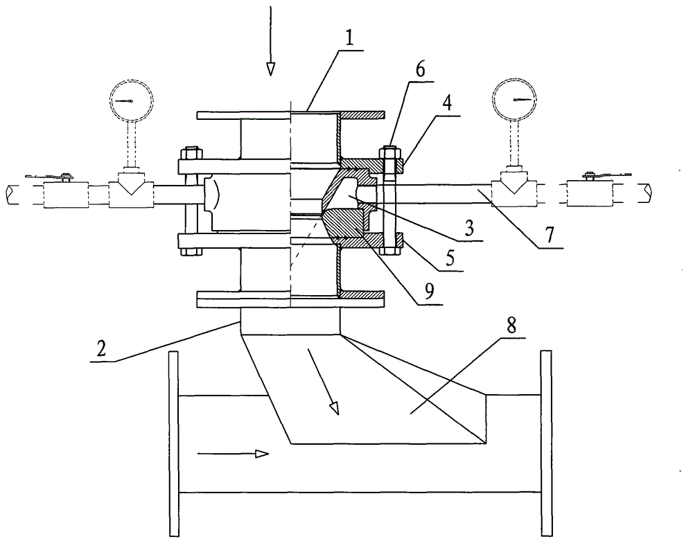
[0014] like figure 1 as shown,

[0015] A ring-shaped wind-locking and flow-aiding device, comprising a material inlet 1 and a material outlet 2, an annular air chamber 3 is arranged between the material inlet 1 and the material outlet 2, and an upper flange is arranged around the upper part of the annular air chamber 3 4. There is a lower flange 5 around the lower part, and the upper flange 4 and the lower flange 5 are fixed by bolts 6. There is a compressed gas pipe 7 on both sides of the annular air chamber 3, and a Venturi jet tube 8. An air chamber sealing ring 9 is provided between the lower flange 5 and the annular air chamber 3 . A tapered annular gap is formed between the annular air chamber 3 and the air chamber sealing ring 9 . Th...


PUM


Abstract

The invention discloses an annular air-locking flow-aiding device, which is mainly used for locking air on powder conveying equipment. The device comprises a feed inlet and a discharge opening, and is characterized in that an annular air chamber is arranged between the feed inlet and the discharge opening, upper flanges are arranged around the upper part of the annular air chamber, lower flanges are arranged around the lower part of the annular air chamber, the upper flanges and the lower flanges are fixed through bolts, compressed air pipes are respectively arranged on two sides of the annular air chamber, and a Venturi jet pipe is arranged below the discharge opening; an air chamber sealing ring is arranged between each lower flange and the annular air chamber; an conical surface annular gap is formed between the annular air chamber and each air chamber sealing ring; the angle of the conical surface annular gap between the annular air chamber and each air chamber sealing ring is 60 degrees; the air pressure input by the compressed air pipes is between 0.2 to 1.0 MPa. The annular air-locking flow-aiding device disclosed by the invention has the advantages of simple and compact structure, good air locking effect, and further capability of increasing the feeding speed.

Description

technical field [0001] The invention relates to an annular air lock and flow aid device, which is mainly used for air lock on powder conveying equipment. Background technique [0002] In the pneumatic conveying of powdery materials, air lock devices are usually used. Currently known air lock devices include air lock pumps (screw pumps), air lock valves and other equipment. Larger, when the flow rate is greater than 3t / h (taking coal powder as an example), the air lock effect is ideal, and the investment and output are more cost-effective; but when the flow rate is less than 3t / h (taking coal powder as an example), the traditional The wind-locking equipment has a poor wind-locking effect, and the investment and output are relatively small. [0003] At present, the air-locking equipment for small-flow powder transportation is generally made of injection pipes based on the principle of Venturi tubes. Due to the different lengths and thicknesses of pipes on industrial sites, th...

Claims


Application Information

Patent Timeline
Patent Type & Authority Applications(China)
IPC IPC(8): B65G53/66
Inventor 左召明储李德李童玉朱旺水张武彩
Owner HEFEI GOODTIMES AUTOMATION
Why Eureka
Try Eureka