Solid waste recycling and crushing device

A technology of crushing device and crushing roller, which is used in solid separation, chemical instruments and methods, grain processing, etc. Improve the performance of use, the effect of rapid particle discharge

Pending Publication Date: 2022-01-04
刘智慧
View PDF6 Cites 0 Cited by
  • Summary
  • Abstract
  • Description
  • Claims
  • Application Information

AI Technical Summary

Problems solved by technology

[0005] Aiming at the deficiencies of the prior art, the present invention provides a solid waste recycling crushing device, which solves the problem that the traditional solid waste crushing device will fall off dust, dust, water and other sundries attached to the surface of solid waste during the crushing process. However, under the force of these debris when crushing, the debris will adhere to the screen of the equipment, which is prone to blockage, and in severe cases, the entire equipment will not work normally and reduce the performance.

Method used


Image

  • Solid waste recycling and crushing device
  • Solid waste recycling and crushing device
  • Solid waste recycling and crushing device

Examples


Embodiment example 1

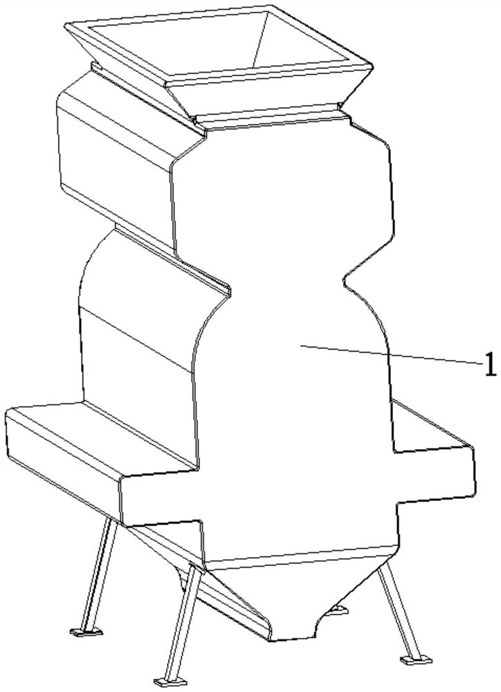
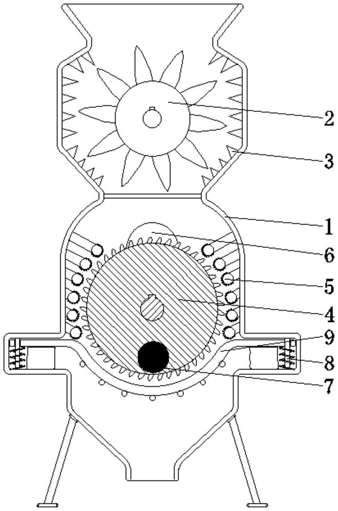
[0030] see Figure 1-7 , the present invention provides a technical solution: a solid waste recycling crushing device, including a shell 1, and the inside of the shell 1 is provided with a crushing roller 2, crushing teeth 3, abrasive rollers 4, grinding teeth 5, cams 6, and magnetic rods 7 , guide rod 8, sieve plate device 9, the crushing roller 2 is rotatably connected inside the casing 1 and close to the top position, the crushing teeth 3 are arranged on the inner wall of the casing 1 and located at the position of the crushing roller 2, and the abrasive roller 4 is rotatably connected to the casing 1 Inside and close to the bottom position, the grinding teeth 5 are arranged on the inner wall of the shell 1 and located at the position of the abrasive roller 4, the cam 6 is fixed on one end of the abrasive roller 4, the magnetic rod 7 is arranged inside the abrasive roller 4 and close to the position, and the sieve plate The device 9 is set on the inner wall of the housing 1...

Embodiment example 2

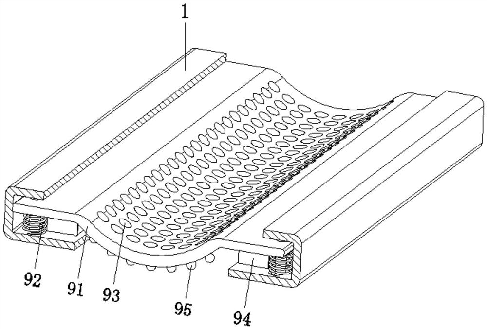
[0032] The sieve plate device 9 is provided with a sieve plate main body 91, a spring 92, a leakage hole 93, an air injection device 94, and a magnetic impact device 95. Between the corresponding two sides of the inner wall of the shell 1 and on the surface of the guide rod 8, the leakage hole 93 is opened on the surface of the sieve plate main body 91, the air injection device 94 is arranged at the bottom of the sieve plate main body 91, and the magnetic impact device 95 is arranged on the sieve plate main body 91. The bottom of the main body 91 and the position close to the leakage hole 93 are rotated by the abrasive roller 4, and the cam 6 and the magnetic bar 7 are rotated accordingly. After receiving the repelling magnetic force, the magnetic impact device 95 will impact the main body 91 of the sieve plate, thereby generating Vibration helps the dust to fall off automatically, and the rotating cam 6 will press the main body 91 of the sieve plate, so that the air injection ...

Embodiment example 3

[0034] The air injection device 94 is provided with a strip-shaped bag 941, a main air passage 942, and an arc-shaped conical hole 943. The strip-shaped bag 941 is arranged between the two sides corresponding to the bottom edge of the sieve plate main body 91 and the inner wall of the shell 1, and the main air passage 942 is opened. Inside the sieve plate main body 91, and the arc-shaped tapered hole 943 is inside the sieve plate main body 91 and is located at the position of the leakage hole 93. When the cam 6 rotates under the drive of the abrasive roller 4, the sieve plate main body 91 will be intermittently The strip-shaped bag 941 is compressed, and the interior is quickly discharged, and conveyed by the main air channel 942, and then ejected from the arc-shaped cone hole 943 to the leakage hole 93, which is helpful for the simultaneous removal of dust and solid waste particles. Blowing reduces the stickiness of dust and facilitates discharge, making it less prone to clogg...


PUM


Abstract

The invention discloses a solid waste recycling and crushing device. The device comprises a shell, a crushing roller is rotationally connected to the position, close to the top, in the shell, crushing teeth are arranged on the inner wall of the shell and located at the position of the crushing roller, and a grinding roller is rotationally connected to the position, close to the bottom, in the shell. Grinding teeth are arranged on the inner wall of the shell and located at the position of the grinding roller, a cam is fixed to one end of the grinding roller, a magnetic bar is arranged at the position, close to the bottom, in the grinding roller, and a sieve plate device is arranged at the position, close to the grinding roller, of the inner wall of the shell and is in sliding connection with the inner wall of the shell through a guide rod. The invention relates to the technical field of solid waste crushing equipment. According to the solid waste recycling and crushing device, the effect of preventing dust adhesion is achieved, dust can be rapidly cleaned away in time, adhesion and accumulation are reduced, the blocking condition is avoided, crushing of solid waste is facilitated, and the working efficiency and the using performance are improved.

Description

technical field [0001] The invention relates to the technical field of solid waste crushing equipment, in particular to a solid waste recycling crushing device. Background technique [0002] Solid waste refers to the solid, semi-solid, and gaseous items placed in containers that lose their original use value or have not lost their use value but are discarded or abandoned during production, living and other activities. Articles and substances that are included in waste management according to administrative regulations. Liquid wastes that cannot be discharged into water bodies and gaseous substances placed in containers that cannot be discharged into the atmosphere. Because most of them are more harmful, they are generally classified into the solid waste management system. There are many ways to classify solid waste. According to its composition, it can be divided into organic waste and inorganic waste; according to its form, it can be divided into solid waste, semi-solid w...

Claims


Application Information

Patent Timeline
IPC IPC(8): B02C4/10B02C4/28B02C23/16B07B1/28B07B1/42
CPCB02C4/10B02C4/28B02C23/16B07B1/28B07B1/42B02C2201/06B02C2023/165
Inventor 刘智慧
Owner 刘智慧
Why Eureka
Try Eureka