Biomass granular fuel preparation device

A technology for the preparation of biomass particles and fuels, which is applied in the direction of biofuels, waste fuels, fuels, etc., can solve the problems of complicated operations, uneven pressure on particles, and restrictions on the application and development of biomass fuels, so as to prevent spillage and prevent The effect of jamming and reducing the operation process

Inactive Publication Date: 2020-05-19
NORTHWEST A & F UNIV
View PDF0 Cites 0 Cited by
  • Summary
  • Abstract
  • Description
  • Claims
  • Application Information

AI Technical Summary

Problems solved by technology

The traditional biomass pellet fuel preparation mold is mostly composed of a punch, a barrel, a mold pad, and a stripper. The structure is simple, but the operation is complicated, and the separation of the mold pad and the barrel often causes uneven force on the pellets, which affects the biomass. The production quality of fuel restricts the application and development of biomass fuel in the market

Method used


Image

  • Biomass granular fuel preparation device
  • Biomass granular fuel preparation device
  • Biomass granular fuel preparation device

Examples


Embodiment 1

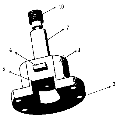
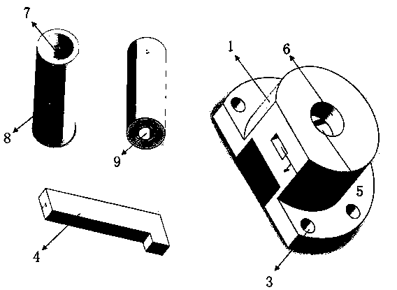
[0019] A kind of biomass particle fuel preparation device, as attached figure 1 And attached figure 2 As shown, it consists of base (1), discharge port (2), fixing hole (3), pull-out stripping plate (4), stripping plate track (5), barrel holder (6), barrel ( 7), barrel inlet (8), barrel outlet (9) and punch (10). The punch (10) is inserted into the barrel (7) from the feed port (8) of the barrel; the barrel (7) is placed in the center of the upper layer of the base (1) and fixed in the barrel holder (6); The lower part of the card seat (6) faces the stripping plate track (5) and the barrel outlet (9) in turn; the stripping plate track (5) runs through the upper layer of the base (1) in the radial direction, and the pull-out stripping plate (4) inserted therebetween; four fixing holes (3) are provided on the lower layer of the base (1) for device fixing.

[0020] Among them, the diameter of the upper layer of the base (1) is 105 mm, and the height is 50 mm; the diameter of ...

Embodiment 2

[0022] A method for preparing corn stalk pellet fuel by using the biomass pellet fuel preparation device:

[0023] First, corn stalks were selected as raw materials, and the corn stalks were crushed to make the particle size less than 80 meshes, and then placed in an oven at 105 °C for 24 hours. Because moisture is a natural binder, it can improve the mechanical strength of the granular fuel, so before starting to press the pellets, add 10% moisture to the crushed and dried raw materials and mix them evenly. Then, weigh 1g of the raw material after the above treatment, slide it into the barrel (7) along the inclined surface of the barrel feed port (8) of the biomass particle fuel preparation device, and then prepare the biomass particle fuel The device is fixed on the universal testing machine, and the pressure is gradually increased. After the pressure reaches 5MPa, the pressure is stopped, and the state is maintained for 2 minutes. Then, the pressure is reduced and the pull-...


PUM

PropertyMeasurementUnit
diameteraaaaaaaaaa
diameteraaaaaaaaaa
heating valueaaaaaaaaaa

Abstract

The invention relates to a biomass granular fuel preparation device. The structure of the biomass granular fuel preparation device mainly comprises a base, a discharge port, a fixing hole, a drawing type demolding plate, a demolding plate track, a material cylinder clamping seat, a material cylinder, a material cylinder feeding port, a material cylinder discharge port and a punch, wherein the punch is inserted from the material cylinder feeding port, and is clamped in the material cylinder clamping seat in the center of the upper layer of the base together with the material cylinder, the lowerportion of the material cylinder clamping seat is over against the demolding plate track and the discharge port, the drawing type demolding plate is inserted from one side of the demolding plate track, and the demolding plate track transversely penetrates through the base along the radial direction. By means of the drawing type demolding plate and the material cylinder clamping seat, the demolding process is simplified, and the stability and the stress uniformity of the granular fuel in the pressing process are guaranteed, so that the quality of the biomass granular fuel is improved while thepreparation efficiency of the biomass granular fuel is improved.

Description

technical field [0001] The invention belongs to the technical field of biomass comprehensive utilization, and in particular relates to a biomass particle fuel preparation device. Background technique [0002] With the shortage of energy and resources and the increasingly serious environmental pollution, the research on the utilization of biomass waste resources has attracted extensive attention. At present, biomass energy is considered as a potential alternative to fossil energy. Agricultural and forestry waste, such as straw and branches, is rich in biomass energy, but farmers still mostly use incineration or direct return to the field to deal with agricultural waste. This not only seriously damages the ecological environment, but also abandons the commercial value of agricultural and forestry waste. [0003] The defects of wide distribution of biomass energy, low energy density, and inconvenient storage and transportation are the main factors limiting its development, so...

Claims


Application Information

Patent Timeline
Patent Type & Authority Applications(China)
IPC IPC(8): C10L5/44B01J2/22
CPCB01J2/22C10L5/44C10L2290/32Y02E50/10Y02E50/30
Inventor 陈潇林菲
Owner NORTHWEST A & F UNIV
Why Eureka
Try Eureka