Friction planetary reducer

A planetary reducer, planetary technology, applied in the direction of friction transmission, transmission, belt/chain/gear, etc., can solve the problems of small transmission ratio, high production cost, complex structure, etc.

Inactive Publication Date: 2018-10-16
温岭市天工工量刃具科技服务中心有限公司
View PDF8 Cites 0 Cited by
  • Summary
  • Abstract
  • Description
  • Claims
  • Application Information

AI Technical Summary

Problems solved by technology

[0004] But the above-mentioned planetary gear reducer is not suitable for the manipulator, the specific reasons are as follows: 1. Since the inner teeth of the planetary gear and the sun shaft and the housing are helical meshing, it is a gear transmission, and the transmission ratio is small, and it cannot be used on the manipulator. 2. Because the transmission is all gear transmission, there is a transmission gap in the transmission process, which leads to low transmission accuracy; 3. The structure is relatively complicated, the production cost is high, and the carrying capacity needs to be improved

Method used


Image

  • Friction planetary reducer
  • Friction planetary reducer
  • Friction planetary reducer

Examples


Embodiment Construction

[0023] The following are specific embodiments of the utility model and in conjunction with the accompanying drawings, the technical solution of the utility model is further described, but the utility model is not limited to these embodiments.

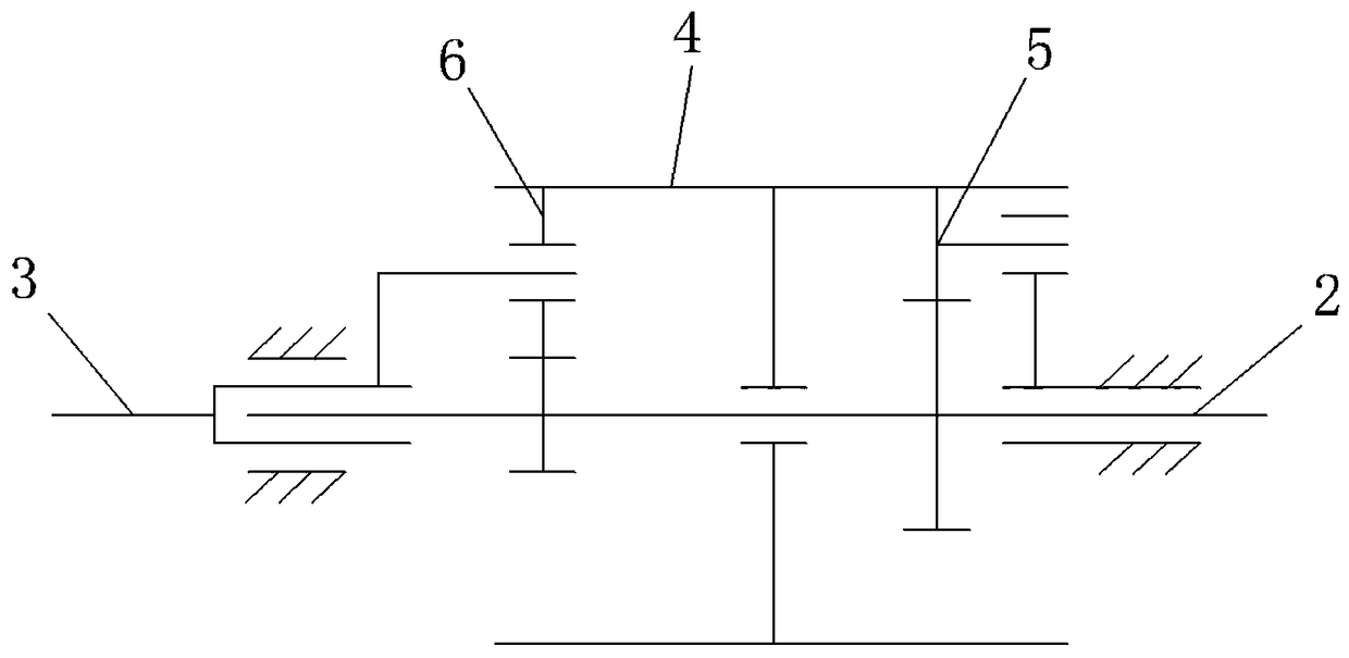
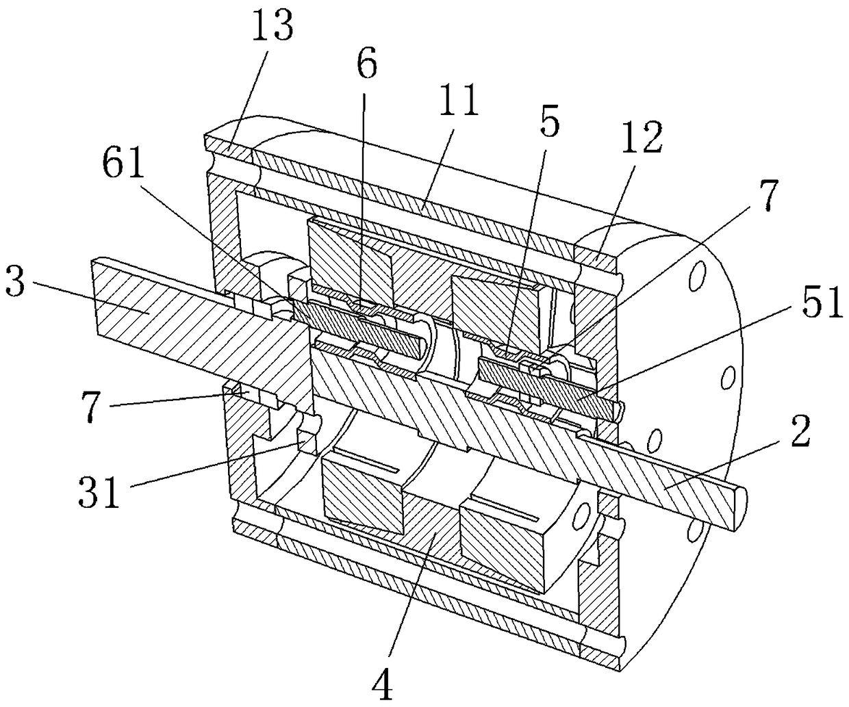
[0024] The friction planetary reducer includes a cylindrical casing 11, an input end cover 12 and an output end cover 13 respectively arranged at both ends of the casing 11, and the shape of the casing 11 is as follows Figure 5 As shown, the housing 11 is connected together with the input end cover 12 and the output end cover 13 by bolts.

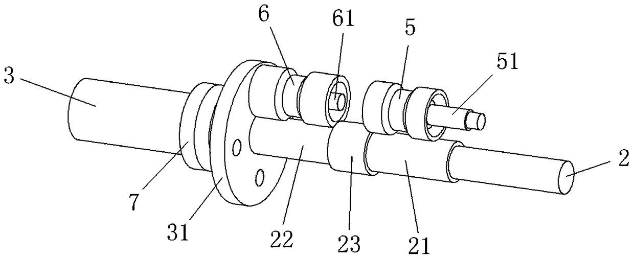
[0025] Such as figure 2 As shown, the casing 11 is pierced with an input shaft 2 and an output shaft 3 coaxially arranged with the casing 11, the input end of the input shaft 2 protrudes to the outside of the input end cover 12, and the output end of the output shaft 3 protrudes from the output The outside of the end cap 13. Specifically, such as image 3 As shown, the middle part of the input s...


PUM


Abstract

The invention provides a friction planetary reducer, belongs to the technical field of machineries, and solves the problem that the conventional gear planetary reducer is small in transmission ratio. The friction planetary reducer comprises a cylindrical shell, an input end cover and an output end cover, wherein the input end cover and the output end cover are arranged at two ends of the shell respectively; an input shaft and an output shaft are arranged in the shell; the middle of the input shaft is provided with an annular step A positioned in the shell; the output end of the input shaft is provided with an annular step B positioned in the shell; a flexible cylinder, with which the input shaft is sleeved, is arranged in the shell; a plurality of fixed flexible gears coaxial with the input shaft are arranged between the flexible cylinder and the annular step A; a rotating shaft A, one end of which is fixed on the input end cover, is arranged in each fixed flexible gear; a plurality of planetary flexible gears coaxial with the input shaft are arranged between the flexible cylinder and the annular step B; a rotating shaft B, one end of which is fixed on the output shaft, is arranged in each planetary flexible gear. The friction planetary reducer has the advantages of being large in transmission ratio, simple in structure, and the like.

Description

technical field [0001] The utility model belongs to the technical field of machinery and relates to a friction planetary reducer, in particular to a friction planetary reducer suitable for manipulators. Background technique [0002] Commonly used reducers mainly include ordinary cylindrical gear reducers, worm gear reducers and planetary gear reducers. Faced with increasingly diverse transmission forms and power requirements, commonly used reducers can no longer meet the needs of production, and the problems exposed are becoming more and more serious. more obvious. Ordinary cylindrical gear reducer, although the structure is relatively simple, but the degree of coincidence is not high, often need to use gear displacement modification to meet the transmission requirements, ordinary cylindrical gear reducer with large transmission ratio is bulky and heavy, which is not conducive to the improvement of power performance Improvement; planetary gear reducer has the characteristic...

Claims


Application Information

Patent Timeline
Patent Type & Authority Patents(China)
IPC IPC(8): F16H13/08F16H57/08
CPCF16H13/08F16H13/10F16H57/08
Inventor 李绣峰
Owner 温岭市天工工量刃具科技服务中心有限公司
Why Eureka
Try Eureka