Novel tunnel non-contact deformation monitoring method

A deformation monitoring, non-contact technology, applied in the direction of measuring devices, instruments, optical devices, etc., can solve the problems of high human resource requirements, affect the construction progress, take 10 minutes or even longer, and achieve human resource consumption Minimize and avoid data loss and damage

Active Publication Date: 2014-09-24
重庆市建筑科学研究院有限公司
View PDF5 Cites 11 Cited by
  • Summary
  • Abstract
  • Description
  • Claims
  • Application Information

AI Technical Summary

Problems solved by technology

[0005] This method has disadvantages such as high requirements for human resources, affecting the construction progress, monitoring data is greatly affected by human beings and the number is small, and the measuring points are easily damaged. Since the layout and measurement of measuring points are completely carried out by manpower, each monitoring takes 1-2 hours. Humans operate at the same time, so monitoring personnel are required to be stationed at the construction site. At the same time, the monitoring data depends on manual reading. Different monitoring personnel may cause human errors in the readings. It takes 10 minutes or even longer to monitor the deformation value of a section.
Therefore, the amount of monitoring data is often not enough to guide design and construction.
At the same time, it is necessary to pull the steel ruler in multiple directions in the tunnel monitoring section during monitoring, which affects the movement of construction vehicles and the safety of personnel
Since the monitoring measuring points are exposed to the surface of the tunnel lining for a long time, it is easy to damage the measuring points during the tunnel construction process and affect the monitoring data

Method used


Image

  • Novel tunnel non-contact deformation monitoring method
  • Novel tunnel non-contact deformation monitoring method
  • Novel tunnel non-contact deformation monitoring method

Examples


Embodiment 1

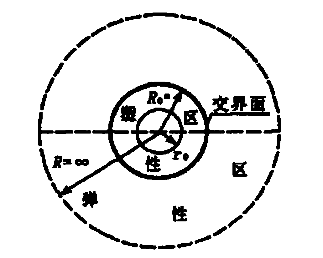
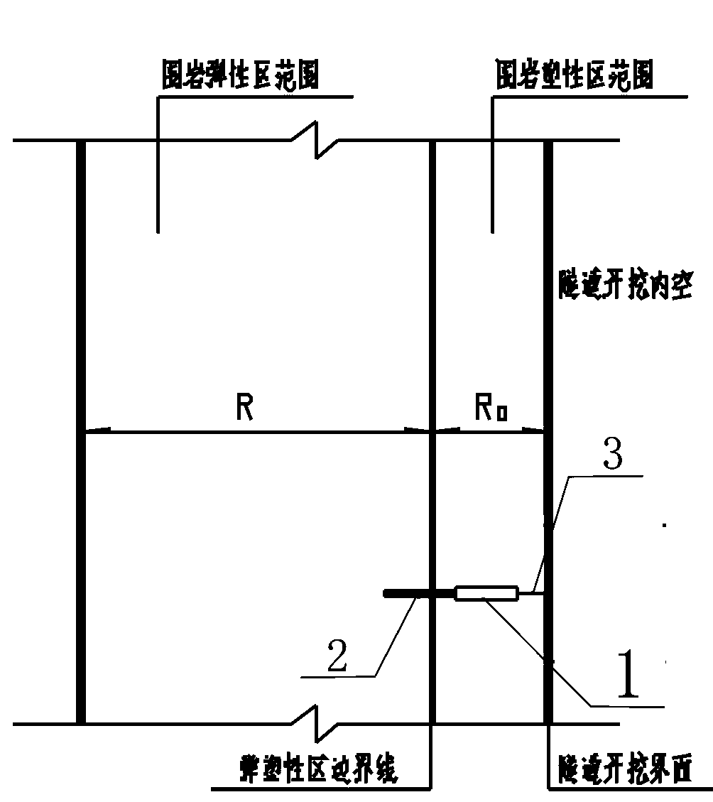
[0036] Embodiment 1: as figure 1 and figure 2 As shown, the deformation of the surrounding rock around the tunnel after excavation can be divided into an elastic zone and a plastic zone, and the deformation monitoring data used to guide design and construction is mainly the plastic deformation of the surrounding rock.

[0037] like figure 2 As shown in , the anchor end of the displacement sensor is embedded in the elastic zone through the interface of the elastic-plastic zone and fixed. Fix the top of the telescopic probe at the sensor end, that is, the active point, to the tunnel excavation interface. Therefore, the deformation value in the R0 range between the tunnel excavation interface and the elastic-plastic zone interface can be effectively tested.

[0038] Before the sensor is buried, it is necessary to first determine the boundary of the plastic zone of the tunnel, that is, the value of R0. The unified strength criterion can consider the influence of the intermedi...


PUM

PropertyMeasurementUnit
Depthaaaaaaaaaa

Abstract

The invention discloses a tunnel rock soil deformation monitoring method, and particularly discloses a novel tunnel non-contact deformation monitoring method. A thickness R0 value of a plastic area is calculated. A sensor installing hole is drilled in a surrounding rock. One anchoring end is arranged at the tail end of an optical fiber single point displacement sensor. The anchoring end penetrates from the installing hole through the plastic area to be buried in an elastic area and fixed. The optical fiber single point displacement sensor is arranged in the plastic area. The top end, i.e. a flexible point, of a telescoping probe of the sensor is fixed on a tunnel excavation interface and used for measuring data. Deformation of the plastic area is calculated according to the value measured by the optical fiber single point displacement sensor. The monitoring data are transmitted to a tunnel port via optical fibers. During the process, consumption of manpower resource is low, the monitoring data are not manually influenced, loss and damage of the data in cable transmission can be effectively avoided, and an objective of automatic real-time monitoring can be realized via arrangement of the sensor device.

Description

technical field [0001] The invention relates to the field of deformation monitoring of rock and soil tunnel chambers, in particular to a novel non-contact deformation monitoring method for tunnels. Background technique [0002] Since the advent of the new Austrian method technology, the tunnel design and construction technology has made great progress. The characteristic of the new Austrian method to construct the tunnel is to dynamically monitor the surrounding rock of the tunnel with the help of on-site monitoring, and guide the excavation and support of the tunnel accordingly. Design and construction of protective structures. [0003] At present, the design work of the new Austrian method is under the guidance of its theoretical basis, after the preliminary selection of the design with reference to the design parameters of the built project, and then through the monitoring and analysis of the surrounding rock during the construction process to improve the design. Therefo...

Claims


Application Information

Patent Timeline
IPC IPC(8): G01B11/16
Inventor 孔凡林李成芳李昕
Owner 重庆市建筑科学研究院有限公司
Why Eureka
Try Eureka