Angle connector, connector assemble and communication assembly

A technology for connector components and communication components, which is applied in the direction of connection, fixed connection, contact components, etc., can solve the problems of low signal transmission efficiency, increased cost of communication products, complex structure of communication products, etc., and achieves high signal transmission rate and simple structure. Effect

Inactive Publication Date: 2014-09-24
HUAWEI TECH CO LTD
View PDF6 Cites 3 Cited by
  • Summary
  • Abstract
  • Description
  • Claims
  • Application Information

AI Technical Summary

Problems solved by technology

The connection between multiple line card PCBs and the backplane is realized through multiple bent connectors. In the prior art, since the bent connector only includes two ports, the line card PCB and the bent connector are a pair One relationship, that is, a line card PCB is connected to the backplane through an angled connector. As the functionality of communication products increases, the number of line card PCBs inside will also increase, so the number of angled connectors will also increase. Increase, so the internal structure of communication products is complicated, and the cost of communication products will also increase due to the increase in the number of connectors
Since each angled connector in the prior art can only connect one line card PCB to the backplane, for a single angled connector, only one chip on the line card PCB can be electrically connected to the backplane to realize line The signal transmission between the chip on the card PCB and the backplane, so the signal transmission efficiency is low

Method used


Image

  • Angle connector, connector assemble and communication assembly
  • Angle connector, connector assemble and communication assembly
  • Angle connector, connector assemble and communication assembly

Examples


Embodiment Construction

[0032]The following will clearly and completely describe the technical solutions in the embodiments of the present invention with reference to the accompanying drawings in the embodiments of the present invention. Obviously, the described embodiments are only some, not all, embodiments of the present invention. Based on the embodiments of the present invention, all other embodiments obtained by persons of ordinary skill in the art without creative efforts fall within the protection scope of the present invention.

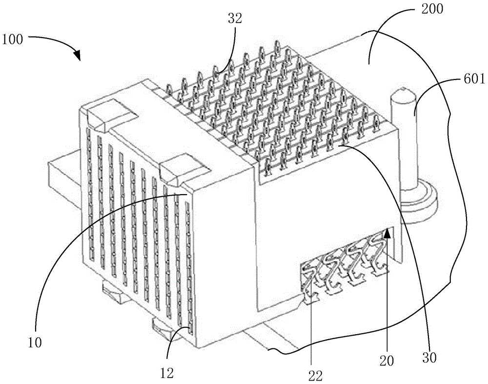
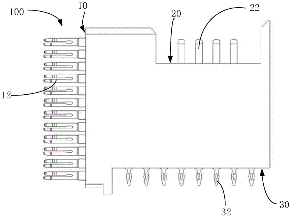
[0033] see figure 1 with figure 2 , the angled connector 100 in an embodiment of the present invention is applied to communication equipment to realize signal transmission between circuit boards in the communication equipment. In this embodiment, the angled connector 100 realizes wire snap Board 200, line card backplane 300 and backplane 400 are electrically connected, such as Figure 9 shown. The curved connector 100 includes a first contact surface 10, a secon...


PUM


Abstract

The invention discloses an angle connector. The angle connector comprises a first contact face, a second contact face and a third contact face, wherein the first contact face, the second contact face and the third contact face are on different surfaces. The angle connector further comprises a first contact portion, a second contact portion and a third contact portion, the first contact portion is arranged on the first contact face and is used for being electrically connected with a back plate, the second contact portion is arranged on the second contact face and is used for being electrically connected with a wire clamp buckling plate, and the third contact portion is arranged on the third contact face and is used for being electrically connected with a wire clamp bottom plate. The angle connector is used for transmitting signals of the wire clamp buckling plate to the back plate and transmitting signals of the wire clamp bottom plate to the back plate. The invention further provides a connector assembly including the angle connector and a communication assembly. By means of the angle connector, the signals of the wire clamp buckling plate and the signals of the wire clamp bottom plate can be received and directly connected to the back plate simultaneously, the structure is simple and the angle connector has the advantage of high signal transmission speed.

Description

technical field [0001] The invention relates to a connector, in particular to an angled connector and a connector assembly for simultaneously connecting a line card buckle plate and a line card bottom plate to a back plate. Background technique [0002] Currently, in some large-scale electronic equipment or communication systems, data and signals between multiple line card PCBs (printed circuit boards, printed circuit boards) and the main board are connected through the backplane. The connection between multiple line card PCBs and the backplane is realized through multiple bent connectors. In the prior art, since the bent connector only includes two ports, the line card PCB and the bent connector are a pair One relationship, that is, a line card PCB is connected to the backplane through an angled connector. As the functionality of communication products increases, the number of line card PCBs inside will also increase, so the number of angled connectors will also increase. ...

Claims


Application Information

Patent Timeline
Patent Type & Authority Applications(China)
IPC IPC(8): H01R13/02H01R12/52
Inventor 莫道春汪泽文张国栋
Owner HUAWEI TECH CO LTD
Why Eureka
Try Eureka