Connector locking device

A locking device and connector technology, which is applied to the parts, connections, coupling devices and other directions of the connecting device, can solve the problems of large space occupation, high manufacturing cost, large volume, etc., and achieves convenient locking and unlocking, convenient operation and volume. small effect

Inactive Publication Date: 2014-09-24
ADC TELECOMM (SHANGHAI) DISTRIBUTION CO LTD
View PDF11 Cites 47 Cited by
  • Summary
  • Abstract
  • Description
  • Claims
  • Application Information

AI Technical Summary

Problems solved by technology

[0003] However, this existing cabinet has the problems of large volume, large space occupation and high manufacturing cost, and because the arrangement density of the connectors in the cabinet is relatively high, it is easy for the connectors to interfere with each other during operation , not convenient for connector management

Method used


Image

  • Connector locking device
  • Connector locking device
  • Connector locking device

Examples


Embodiment Construction

[0030] Exemplary embodiments of the present invention are described in detail below, examples of which are illustrated in the accompanying drawings, wherein the same or similar reference numerals designate the same or similar elements. The embodiments described below with reference to the figures are exemplary and are intended to explain the present invention, and should not be construed as limiting the present invention.

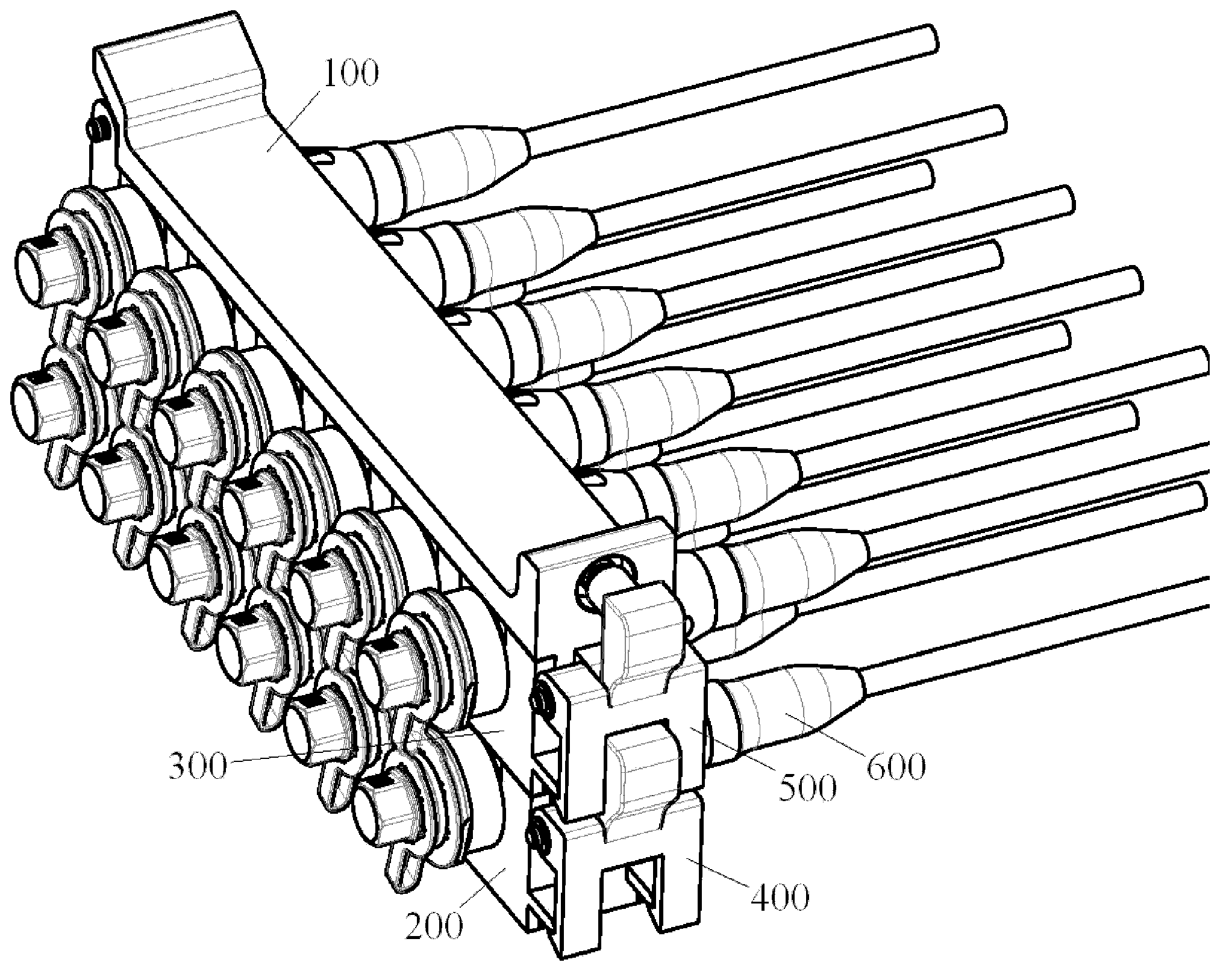
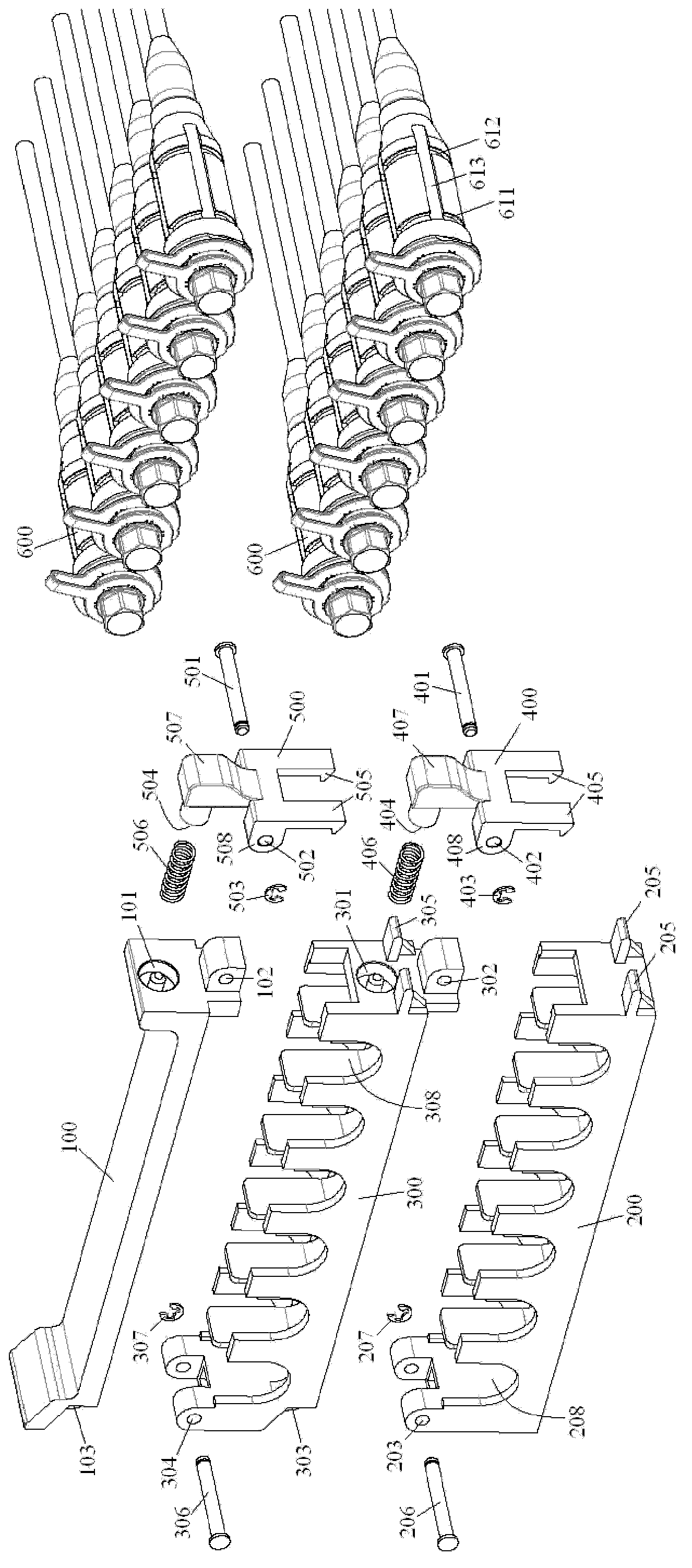
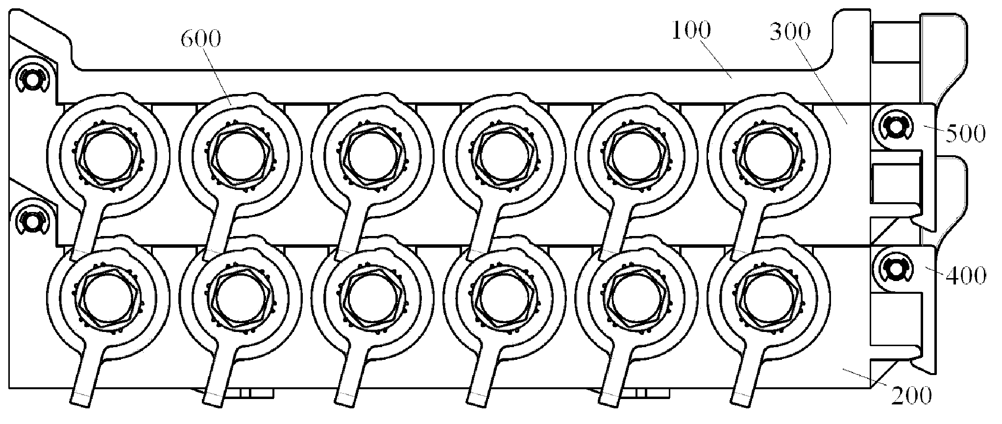
[0031] figure 1 An assembled perspective view showing a connector locking device according to an embodiment of the present invention; figure 2 show figure 1 The perspective exploded schematic diagram of the connector locking device shown; image 3 show figure 1 End view of connector locking device shown.

[0032] Such as figure 1 , figure 2 and image 3 As shown, the connector locking device mainly includes: a plurality of brackets 200 , 300 stacked up and down; and a bracket cover 100 located on the uppermost bracket 300 .

[0033] Such as figu...


PUM


Abstract

The invention discloses a connector locking device. The connector locking device comprises at least one bracket and a bracket cover which is located on the bracket at the top. A row of accommodation grooves with upward openings is formed on each bracket. A connector can be releasably locked in an accommodation groove. When a number of brackets are arranged, any two adjacent brackets are releasably locked together. The bracket cover and the bracket at the top are releasably locked together. According to the invention, any bracket can be conveniently opened, and the connectors locked in the bracket can be operated; compared with a cabinet in the prior art, the connector locking device has the advantages of small volume and convenient operation; and in addition, the connectors and the accommodation grooves of the bracket can be conveniently locked and unlocked.

Description

technical field [0001] The invention relates to a connector locking device, in particular to a locking device for simultaneously locking multiple connectors. Background technique [0002] In the prior art, when it is necessary to manage and lock batches of connectors, it is generally necessary to provide a cabinet specially used for managing and locking batches of connectors. Rows of card slots are formed inside the cabinet to connect The devices are snapped into these slots respectively. [0003] However, this existing cabinet has the problems of large volume, large space occupation and high manufacturing cost, and because the arrangement density of the connectors in the cabinet is high, it is easy for the connectors to interfere with each other during operation , which is not convenient for connector management. Contents of the invention [0004] In view of the foregoing technical problems in the prior art, the present invention aims to provide a connector locking devi...

Claims


Application Information

Patent Timeline
Patent Type & Authority Applications(China)
IPC IPC(8): H01R13/518
Inventor 范文勇王正斌
Owner ADC TELECOMM (SHANGHAI) DISTRIBUTION CO LTD
Why Eureka
Try Eureka