
Electrical connector and method for producing same

An electrical connector and connector technology, which is applied in the direction of contact manufacturing, connection, clamping/spring connection, etc., can solve the problems of high contact resistance and high resistance of electrical connectors, and achieve the purpose of suppressing sliding distance and reducing sliding wear , The effect of improving electrical reliability

Active Publication Date: 2014-09-24
YAZAKI CORP +1
View PDF15 Cites 16 Cited by
  • Summary
  • Abstract
  • Description
  • Claims
  • Application Information

AI Technical Summary

Problems solved by technology

If the wear powder of Sn is oxidized, the electrical resistance will increase, so there is a possibility that the contact resistance of the electrical connector will increase due to the wear powder

Method used


Image

  • Electrical connector and method for producing same
  • Electrical connector and method for producing same
  • Electrical connector and method for producing same

Examples


Embodiment Construction

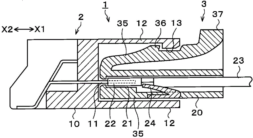
[0036] Hereinafter, an example of the embodiment of the present invention will be described with reference to the drawings. In addition, in this specification and drawings, the same code|symbol is attached|subjected to the component which has substantially the same functional structure, and repeated description is abbreviate|omitted. Such as figure 1 As shown, the electrical connector 1 of this embodiment has a male connector 2 and a female connector 3 that can be freely engaged and disengaged from each other.

[0037] figure 1 The male connector 2 shown on the left has a structure in which a male terminal 11 made of a conductive material protrudes from the front end surface of the male-side resin molded part 10 . A cylindrical male side cover 12 is provided on the male side resin molded part 10 so as to surround the circumference of the male joint 11 . A male locking lock 13 is provided on the inner peripheral surface of the male side cover 12 facing inward.

[0038] on...


PUM


Abstract

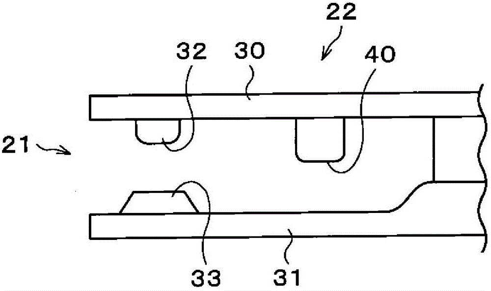
The purpose of the present invention is to provide an electrical connector capable of stable conduction and of minimizing sliding friction as much as possible even when a contact load is small. This electrical connector (1) comprises a male connector (2) and a female connector (3) connected so as to be capable of engaging / disengaging with one another. The male connector (2) is provided with a male tab (11), and the female connector (3) is provided with a housing part (21) into which the male tab (11) is inserted. The housing part (21) is provided with a contact part (30) and a holding part (31) for compressing the male tab (11), and electrically connected to one another. A projection (40) is provided on the contact part (30) and / or the holding part (31). The male tab (11) is provided with a recess (41) capable of accommodating the projection (40). The contact part (30), the holding part (31) and the projection (40) are configured as one component.

Description

technical field [0001] The present invention relates to an electrical connector for easy and reliable electrical connection and disconnection. This case claims priority based on Japanese Patent Application No. 2012-9929 filed in Japan on January 20, 2012 and Japanese Patent Application No. 2013-6912 filed in Japan on January 18, 2013, the contents of which are incorporated herein. Background technique [0002] For example, in electrical connection applications such as automobiles and electronic equipment, electrical connectors in which a female connector and a male connector are freely engaged and disengaged are used. When the electrical connector is connected and disconnected, the male connector on the male connector side inserted into the female connector and the contact piece electrically connected to the male connector on the female connector side slide against each other, causing abrasion. powder. [0003] Usually, Sn plating is applied to the pins on the male connect...

Claims


Application Information

Patent Timeline
Patent Type & Authority Applications(China)
IPC IPC(8): H01R13/04H01R13/03
CPCY10T29/49204H01R13/111H01R13/04H01R4/48H01R43/16H01R13/20
Inventor 中村将寿小野寺晓史菅原章成枝宏人村田达则
Owner YAZAKI CORP
Learn More