Sheet heat sink set equipment

A heat sink and package technology, applied in metal processing equipment, metal processing, hand-held tools, etc., can solve the problems of difficult installation of fin heat sinks, achieve high raw material utilization, high package efficiency, and reduce production costs Effect

Active Publication Date: 2017-01-25
CHANGZHOU MINJIE ELECTRICAL APPLIANCE
View PDF8 Cites 0 Cited by
  • Summary
  • Abstract
  • Description
  • Claims
  • Application Information

AI Technical Summary

Problems solved by technology

[0004] The technical problem to be solved by the present invention is: in order to solve the problem that the installation of the fin heat sink is difficult, the present invention provides a fin heat sink assembly equipment, which uses the helix of the screw to drive the pressure plate, and can easily install the heat sink It is set on the outer wall of the heat transfer tube, on the one hand, it ensures the smooth completion of the set process, and on the other hand, it can increase the fastness between the heat sink and the heat transfer tube

Method used


Image

  • Sheet heat sink set equipment

Examples


Embodiment Construction

[0016] The present invention is described in further detail now in conjunction with accompanying drawing. These drawings are all simplified schematic diagrams, which only illustrate the basic structure of the present invention in a schematic manner, so they only show the configurations related to the present invention.

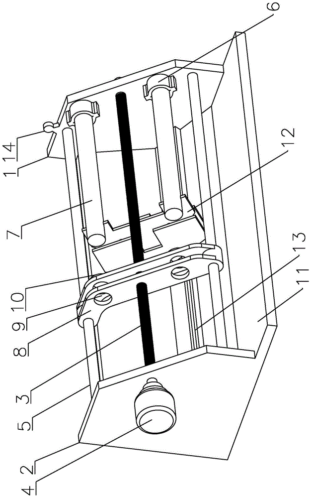
[0017] Such as figure 1 As shown, a chip heat sink set equipment, including:

[0018] Frame, the frame has a first riser 1 and a second riser 2, and a screw rod that is rotatably connected to the first riser 1 and the second riser 2 is passed between the first riser 1 and the second riser 2 3. One end of the screw 3 is provided with a driving motor 4 for driving the rotation of the screw 3, at least one guide rod 5 parallel to the screw 3 is provided between the first vertical plate 1 and the second vertical plate 2, the first vertical plate 1 and the second vertical plate The side walls corresponding to the two vertical plates 2 are provided with a number o...


PUM


Abstract

The invention relates to a device for installing sheet cooling fins in a sleeved mode. The device for installing the sheet cooling fins in the sleeved mode comprises a machine frame and a pressing plate, wherein the machine frame is provided with two vertical plates, a screw which is connected with the two vertical plates in a rotary mode is arranged between the two vertical plates in a penetrating mode, a driving motor is arranged at one end of the screw, a guide rod which is parallel to the screw is arranged between the two vertical plates, a plurality of fixing sleeves used for fixing heat transmission tubes are arranged on the corresponding side walls of the two vertical plates, the cooing fins are arranged in a penetrating mode through the heat transmission tubes, the pressing plate is arranged between the two vertical plates, the screw penetrates through the pressing plate and is connected with the pressing plate in a threaded mode, the guide rod penetrates through the pressing plate and is connected with the pressing plate in a sliding mode, through holes are formed in the pressing plate, the heat transmission tubes can penetrate through the through holes conveniently, and magnets used for fixing the cooling fins are arranged on the edges of the through holes. According to the device for installing the sheet cooling fins in the sleeved mode, the cooling fins can be installed on the outer walls of the heat transmission tubes in the sleeved mode extremely conveniently by driving the pressing plate through the spiral rotation of the screw; meanwhile, the multiple cooling fins can be installed in the sleeved mode at the same time by means of the device, the cooing fins can be installed in the sleeved mode extremely efficiently, the utilization rate of materials is high, and the production cost is greatly reduced.

Description

technical field [0001] The invention relates to the technical field of cooling fin assembly, in particular to a sheet-shaped cooling fin assembly device. Background technique [0002] The heat sink is a device for cooling the heat-prone electronic components in electrical appliances. Because of the increased surface area, the speed of heat absorption and loss is accelerated, and the effect of rapid heat dissipation is achieved through heat transfer. [0003] Most of the existing heat sinks use spiral heat sinks, mainly because the manufacturing process is simple and the installation is convenient, but there are problems such as small heat dissipation area and poor heat dissipation effect. In order to solve the problem of heat dissipation, chip heat sinks are often used. The heat sinks can be circular, square, and rectangular. Large, labor-intensive, time-consuming and costly problems. Contents of the invention [0004] The technical problem to be solved by the present in...

Claims


Application Information

Patent Timeline
Patent Type & Authority Patents(China)
IPC IPC(8): B23P19/00
CPCB25B27/023
Inventor 曹栋礼
Owner CHANGZHOU MINJIE ELECTRICAL APPLIANCE
Why Eureka
Try Eureka