Fixtures for thin-walled parts with lightening holes

A technology of thin-walled parts and weight-reducing holes is applied in the field of fixtures for thin-walled parts with weight-reducing holes, which can solve the problems of waste, affecting production efficiency, easy deformation, etc., and achieves increased equipment investment, reasonable and reliable structural design, and deformation of parts. The effect of reducing the chance of

Inactive Publication Date: 2016-05-04
CHINA NAT HEAVY DUTY TRUCK GROUP DATONG GEARCO
View PDF6 Cites 0 Cited by
  • Summary
  • Abstract
  • Description
  • Claims
  • Application Information

AI Technical Summary

Problems solved by technology

[0004] The present invention provides a fixture for thin-walled parts with weight-reducing holes in order to solve the problems that the existing thin-walled parts with weight-reducing holes are easily deformed, affect production efficiency and cause serious waste.

Method used


Image

  • Fixtures for thin-walled parts with lightening holes

Examples


Embodiment Construction

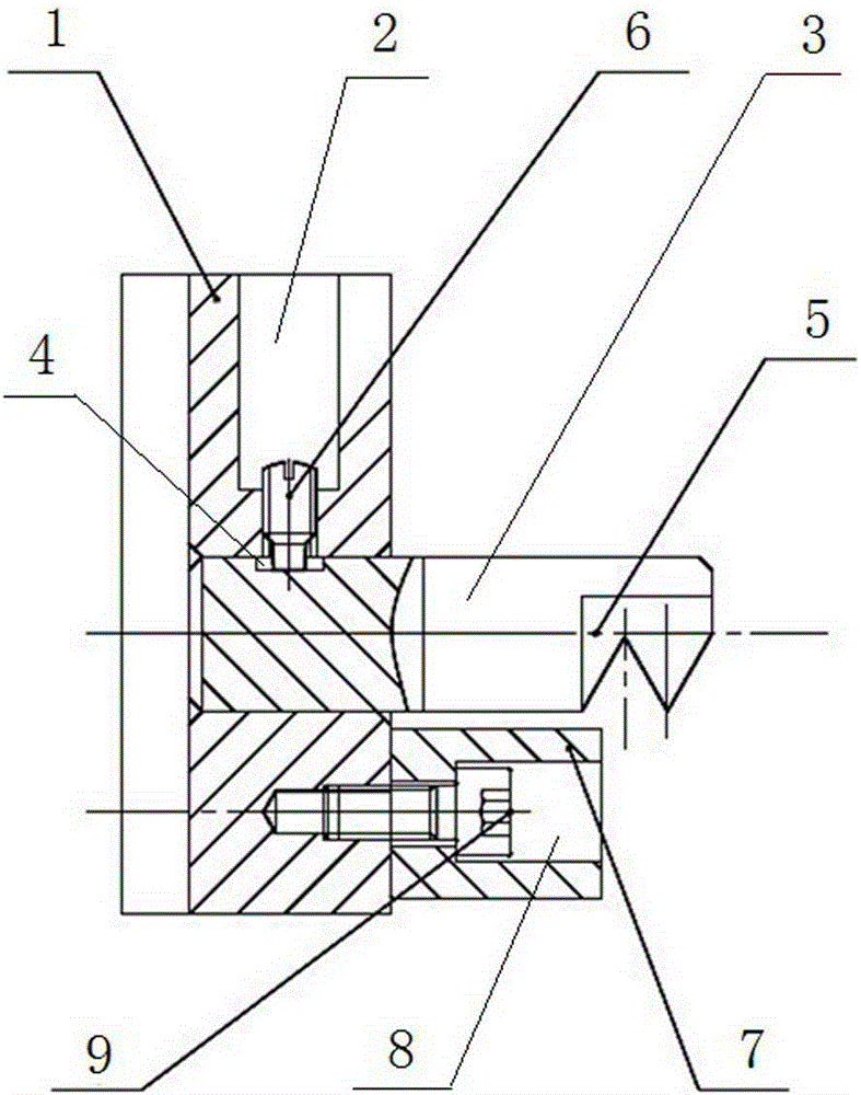
[0010] Fixtures for thin-walled parts with weight-reducing holes, including a rectangular connection base plate 1 connected to each hydraulic chuck female jaw, an adjustment hole is opened in the middle of the connection base plate 1, and one end surface of the connection base plate 1 is opened to communicate with the adjustment hole and Vertical stepped hole 2, a cylindrical chuck rod 3 is pierced in the adjustment hole, a keyway 4 opposite to the position of the stepped hole is opened on the side wall of one end of the chuck rod 3, and a clamping tooth is opened on the side wall of the other end of the chuck rod 3 Groove 5, the set screw 6 that is threadedly connected with it and contacts with the bottom end of keyway 4 is screwed in the step hole 2, and a positioning block 7 is arranged below the clamping alveolar 5, and a step hole I8 is provided on the position block 7, and a step hole I8 is provided in the step hole I8. Screwed with the fastening screw 9 that is connected...


PUM


Abstract

The invention specifically provides a clamp for a thin-walled part with a lightening hole. The problem that an existing thin-walled part with the lightening hole easily deforms, influences the production efficiency and enables waste to be severe during machining is solved. The clamp comprises a rectangular connecting base plate connected with each hydraulic chuck main claw, wherein the middle of the connecting base plate is provided with an adjusting hole, the end face of one end of the connecting base plate is provided with a stepped hole communicated with and perpendicular to the adjusting hole, a column-shaped chuck rod penetrates the adjusting hole, the side wall of one end of the chuck rod is provided with a key groove opposite to the position of the stepped hole, the side wall of the other end of the chuck rod is provided with a clamping alveolar socket, a positioning screw in threaded connection with the stepped hole and in contact with the bottom end of the key groove is screwed in the stepped hole, a positioning block is arranged under the clamping alveolar socket and provided with a stepped hole I, and a fastening screw connected with the connecting base plate is screwed in the stepped hole I. The clamp enables the part deformation possibility to be reduced by higher than 90%, and the production, research and development input cost is reduced.

Description

technical field [0001] The invention relates to an auxiliary device for machining of auto parts, in particular to a fixture for thin-walled parts with weight-reducing holes. Background technique [0002] The auto parts machining industry is facing small profit margins, and customers have higher and higher requirements for products. Thin-walled parts with weight-reducing holes are a new direction that machining companies are constantly exploring. [0003] Existing processing of thin-walled parts with weight-reducing holes mostly uses hydraulic clamping devices to clamp the outside for processing. During the processing, the deformation probability of parts is relatively high, and the utilization rate is low, which affects production efficiency and causes cost. waste. Contents of the invention [0004] In order to solve the problem that the existing thin-walled parts with weight-reducing holes are easily deformed, affect production efficiency and cause serious waste during p...

Claims


Application Information

Patent Timeline
Patent Type & Authority Patents(China)
IPC IPC(8): B23Q3/00
CPCB23Q3/00B23Q2703/04B23Q2703/10
Inventor 任敏朱昆杨国斌师公飞党平王祝山
Owner CHINA NAT HEAVY DUTY TRUCK GROUP DATONG GEARCO
Why Eureka
Try Eureka