Chain for suspending

A technology of chains and chain plates, which is applied in the field of hanging chains, and can solve the problems of insufficient tensile strength of the hanging chains 700

Active Publication Date: 2014-03-26
TSUBAKIMOTO CHAIN CO
View PDF7 Cites 2 Cited by
  • Summary
  • Abstract
  • Description
  • Claims
  • Application Information

AI Technical Summary

Problems solved by technology

[0009] In addition, the structure of the existing first form of hanging chain 700 is that an inner link plate 710 and an outer link plate 720 are respectively arranged on both sides of the chain width direction, so there is a tensile force of the entire hanging chain 700. The possibility of insufficient strength, when the weight of the lifting platform acts on the chain length direction in the form of pulling force, it is possible that the joint of the inner chain plate 710 and the outer chain plate 720 will generate a force that shears the pin shaft 740, making the pin Shaft 740 is curved as indicated by the double-dashed line

Method used


Image

  • Chain for suspending
  • Chain for suspending
  • Chain for suspending

Examples


Embodiment 1

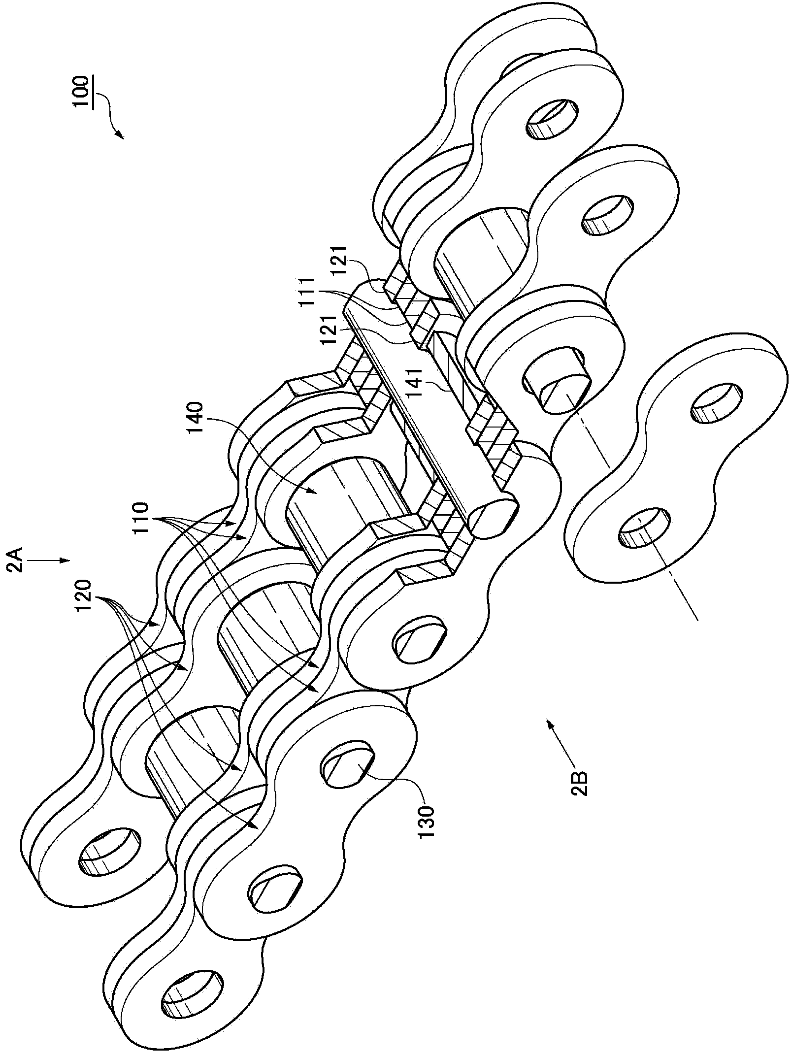
[0051] Refer below Figure 1 to Figure 5 The suspension chain 100 according to the first embodiment of the present invention will be described.

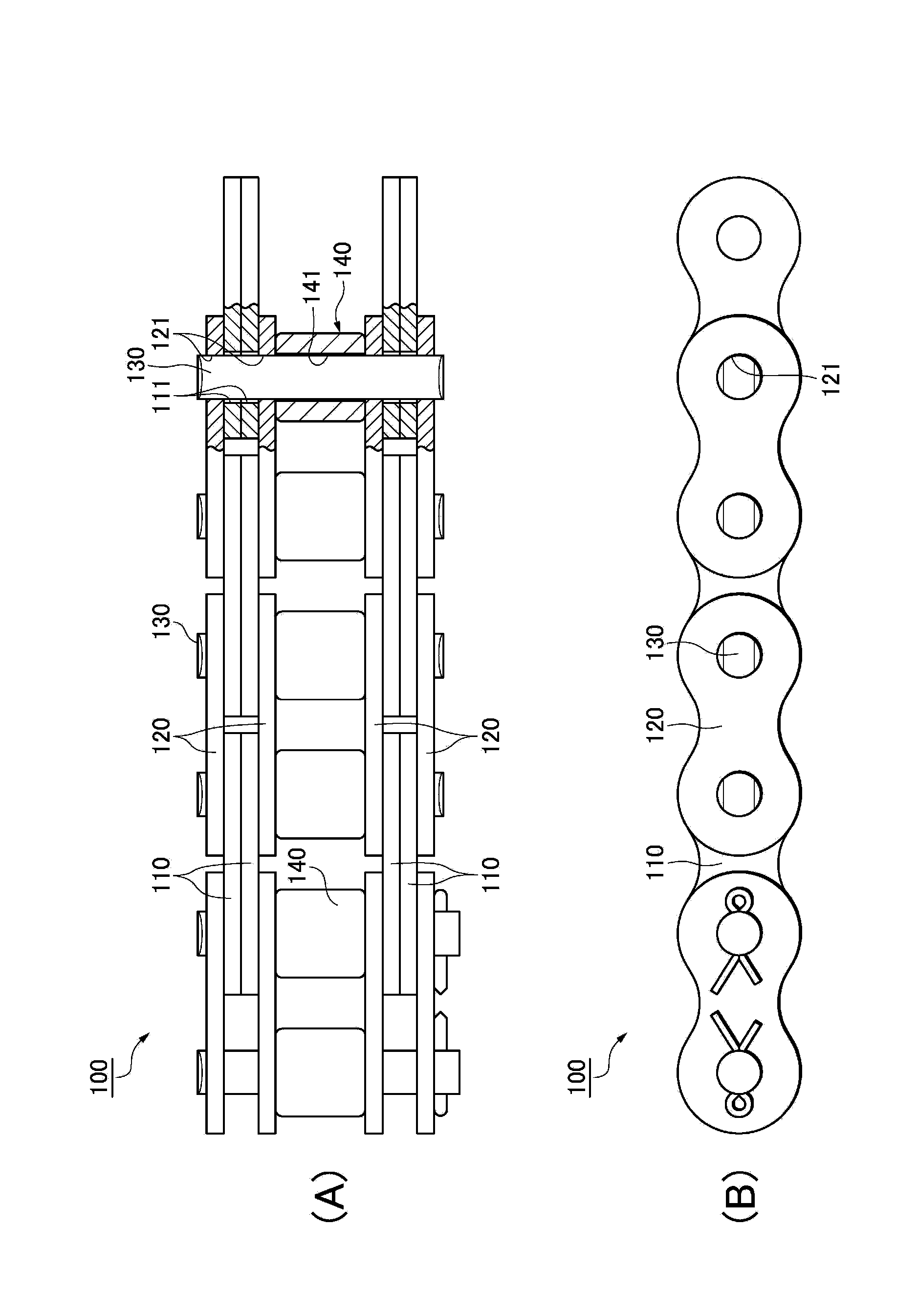
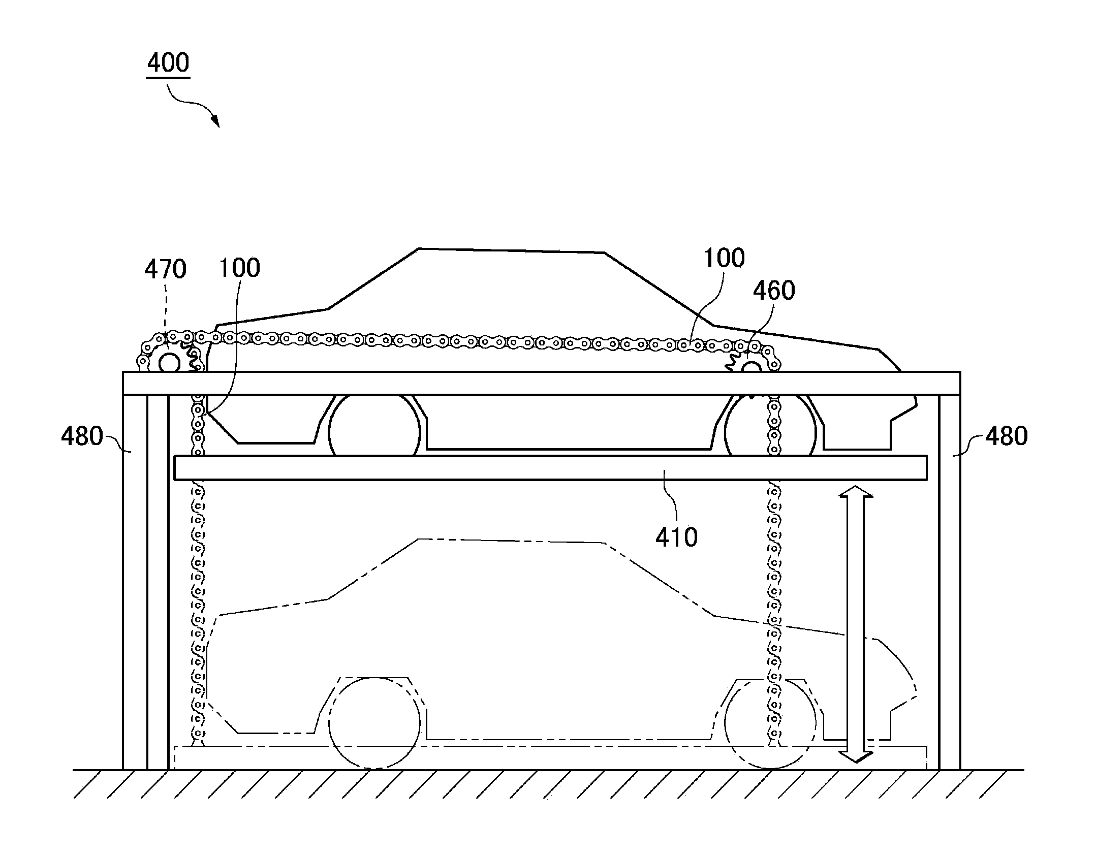
[0052] figure 1 It is a perspective view including a partial cross section of a suspension chain 100 according to the first embodiment of the present invention, figure 2 (A) is from figure 1 A top view of the suspension chain 100 according to the first embodiment of the present invention, which includes a partial cross section, seen from the direction of symbol 2A, figure 2 (B) from figure 1 A side view of the chain 100 for hanging according to the first embodiment of the present invention seen from the direction of symbol 2B, image 3 is used figure 1 A schematic side view of the three-dimensional parking lot 400 of the shown suspension chain 100, Figure 4 yes means image 3 A schematic perspective view of the installation of the hanging chain 100 of the shown three-dimensional parking lot 400, Figure 5 is used fig...

Embodiment 3

[0102] Below, refer to Figure 7 A suspension chain 300 according to a third embodiment of the present invention will be described.

[0103] here, Figure 7 (A) is a plan view including a partial section of a suspension chain 300 according to a third embodiment of the present invention, Figure 7 (B) is from Figure 7 (A) is a side view of the suspension chain 300 according to the third embodiment of the present invention seen from the direction of symbol 7B.

[0104] In addition, in order to facilitate the understanding of the invention, in Figure 7 (A) shows a partial section, but due to the Figure 7 In (B) it is not necessary to express a partial cross section without expressing a partial cross section.

[0105] The hanging chain 300 of the third embodiment is a structure in which the second link plate other than the outermost side of the hanging chain 200 of the second embodiment is replaced with the first link plate. The hanging chains 200 of the example are commo...


PUM


Abstract

The utility model provides a chain (100) for hanging. The chain (100) for hanging is provided with first chain plates (110), second chain plates (120) and a pin shaft (130), wherein the first chain plates (110) are arranged at two outer sides of a roller (140) in the width direction of the chain, the second chain plates (120) are arranged at the two outer sides of the roller in the width direction of the chain and at least the outer sides of the inner sides and the outer sides of the first chain plates in the width direction of the chain, the pin shaft (130) penetrates through a hole (141) of the roller and loose embedding holes (111) of the first chain plates and is embedded in tight embedding holes (121) in the second chain plates, at least two of the first chain plates and at least two of the second chain plates are respectively arranged relative to the single roller at the single side in the width direction of the chain, and the second chain plates are at least arranged at the outermost side. Therefore, compared with a single-line chain, the chain for hanging can reinforce tensile strength. Compared with the structure that only multiple lines of rollers and the chain plates are arranged respectively, the number of parts can be reduced, meanwhile, the width of the chain can be reduced, and miniaturization is realized.

Description

technical field [0001] The present invention relates to a chain for suspension, for example, a chain for suspension for vertically moving a lifting table on which a vehicle is placed in a multi-storey parking lot for vehicles or a chain for suspension for vertically moving a fork-type lifting part of a forklift chain. Background technique [0002] Among the well-known existing chains for hanging, as an example of moving objects in the vertical direction, there is a lift platform for hanging vehicles such as automobiles, motorcycles, bicycles, etc. Chains for suspension that move vertically (for example, Patent Document 1 and Patent Document 2). [0003] As such an existing first type of hanging chain, there are, for example, Figure 8 The hanging chain 700 shown in (A), as the second existing hanging chain, consists of Figure 8 (B) The suspension chain 800 shown. [0004] here, Figure 8 (A) is a top view showing a partial cross section of a conventional suspension chain ...

Claims


Application Information

Patent Timeline
Patent Type & Authority Applications(China)
IPC IPC(8): F16G13/12F16G15/14
CPCF16G13/06
Inventor 生鹰道雄
Owner TSUBAKIMOTO CHAIN CO
Why Eureka
Try Eureka