Vehicle and pull rod type suspension device thereof

A tie-rod mount and mount bracket technology, which is applied in the field of vehicles, can solve the problems of the change of the rigidity of the linear segment of the mount, the loss of the anti-twist function, and the reduction of the fatigue durability of the rubber bushing, so as to improve the reliability and prolong the service life. , Solve the effect of reducing fatigue durability

Active Publication Date: 2014-10-01
GREAT WALL MOTOR CO LTD
View PDF6 Cites 11 Cited by
  • Summary
  • Abstract
  • Description
  • Claims
  • Application Information

AI Technical Summary

Problems solved by technology

[0003] However, when the vehicle is started and turned off, the torsion limit of the powertrain is realized by the structure of the rubber itself on the rubber bushing. When the vehicle is driven for a period of time and the vehicle is in harsh working conditions for a long time, the rubber is easy to age, and the rubber The fatigue durability of the bushing is reduced, so there is a risk of cracking. Moreover, the stiffness of the linear section of the suspension changes, and the NVH (Noise, Vibration, Harshness, noise, vibration, and harshness) effect of the vehicle is reduced, so that the rear suspension of the engine is limited. , Loss of anti-twist function

Method used


Image

  • Vehicle and pull rod type suspension device thereof
  • Vehicle and pull rod type suspension device thereof
  • Vehicle and pull rod type suspension device thereof

Examples


Embodiment Construction

[0034] Embodiments of the present invention are described in detail below, examples of which are shown in the drawings, wherein the same or similar reference numerals designate the same or similar elements or elements having the same or similar functions throughout. The embodiments described below by referring to the figures are exemplary only for explaining the present invention and should not be construed as limiting the present invention.

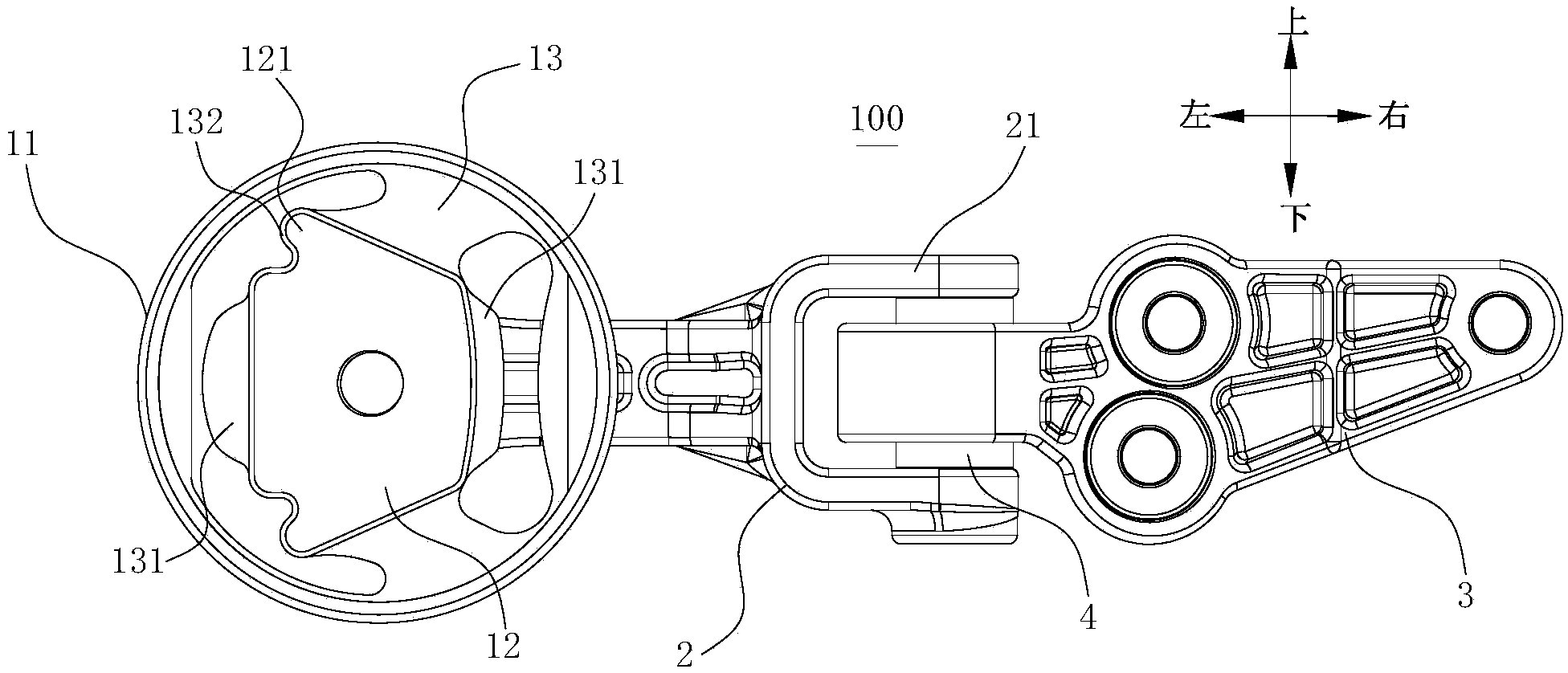
[0035] In describing the present invention, it should be understood that the terms "center", "transverse", "length", "width", "upper", "lower", "left", "right", "vertical", The orientation or positional relationship indicated by "horizontal", "top", "bottom", "inner", "outer", "radial" and "circumferential" are based on the orientation or positional relationship shown in the drawings, and are only In order to facilitate the description of the present invention and simplify the description, it does not indicate or imply that the device or...


PUM


Abstract

The invention discloses a vehicle and a pull rod type suspension device thereof. The pull rod type suspension device comprises a bush assembly, a connecting rod and a transmission mount bracket, wherein the bush assembly comprises an inner core, a rubber part and an outer tube, the inner core is arranged inside the outer pipe, the rubber part is arranged between the outer pipe and the inner core, the side wall of the outer pipe is provided with a first through hole, and the position on the rubber part, which corresponds to the first opening, is provided with a second through opening; one end of the connecting rod penetrates the first opening of the outer pipe and the second opening of the rubber part to be connected with the inner core, and the connecting rod can swing between two opposite side walls relative to the first opening of the outer pipe; the transmission mount bracket is connected with the other end of the connecting rod. The pull rod type suspension device limits torsional displacement of a power assembly of a vehicle through connection of the connecting rod and the inner core and forming of the first opening for limiting movement of the connecting rod on the outer pipe, and solves the problems of aging inclination and reduction of fatigue durability of the bush assembly.

Description

technical field [0001] The invention relates to the field of vehicles, in particular to a vehicle and a pull-rod suspension device thereof. Background technique [0002] In recent years, the domestic sales of SUVs (Sport Utility Vehicles) have been increasing year by year, and they are increasingly popular with consumers. Major OEMs have successively launched new SUVs on the market. Due to the large powertrains carried by SUVs ( Displacement is generally above 2.0), and the weight and torque of the engine mount are relatively large. [0003] However, when the vehicle is started and turned off, the torsion limit of the powertrain is realized by the structure of the rubber itself on the rubber bushing. When the vehicle is driven for a period of time and the vehicle is in harsh working conditions for a long time, the rubber is easy to age, and the rubber The fatigue durability of the bushing is reduced, so there is a risk of cracking. Moreover, the stiffness of the linear sect...

Claims


Application Information

Patent Timeline
Patent Type & Authority Applications(China)
IPC IPC(8): B60K5/12
Inventor 谷玉山杨林王松佘振成郝永生
Owner GREAT WALL MOTOR CO LTD
Why Eureka
Try Eureka