Drawing device and drawing method

A technology of main scanning direction and sub-scanning, which is applied in the direction of exposure device, optics, and optomechanical equipment in the photolithography process, which can solve the problems that the automatic focusing mechanism cannot function normally, and the drawing accuracy of the band-shaped area is reduced, so as to improve the drawing Accuracy, easy parts management, effect of equipment cost reduction

Active Publication Date: 2014-10-01
DAINIPPON SCREEN MTG CO LTD
View PDF8 Cites 4 Cited by
  • Summary
  • Abstract
  • Description
  • Claims
  • Application Information

AI Technical Summary

Problems solved by technology

Therefore, sometimes the autofocus mechanism cannot function properly
Therefore, th

Method used


Image

  • Drawing device and drawing method
  • Drawing device and drawing method
  • Drawing device and drawing method

Examples


Example Embodiment

[0068] Hereinafter, embodiments of the present invention will be described with reference to the drawings. In addition, in the drawings, in order to facilitate understanding, the size and number of each part may be exaggerated or simplified.

[0069]

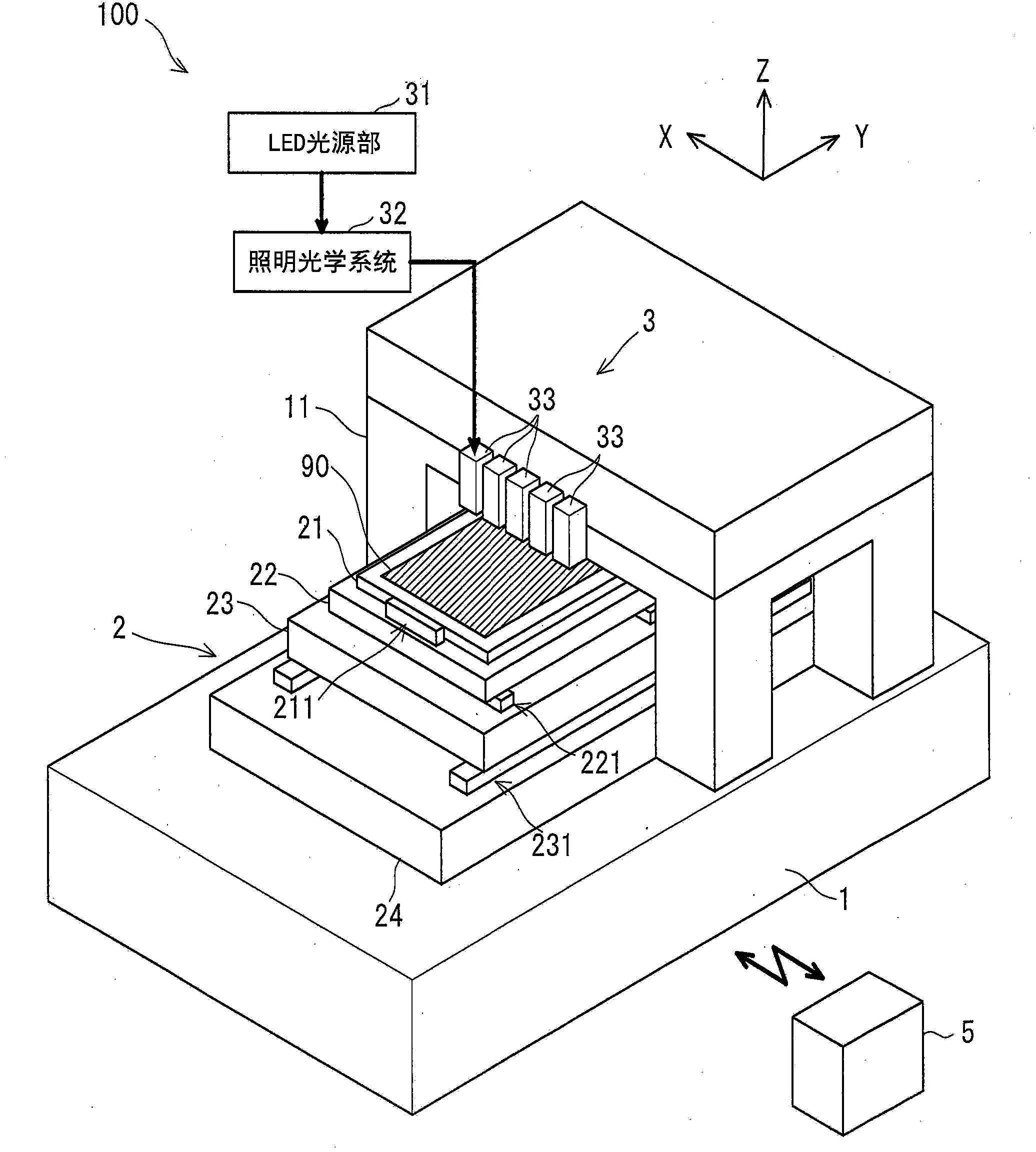
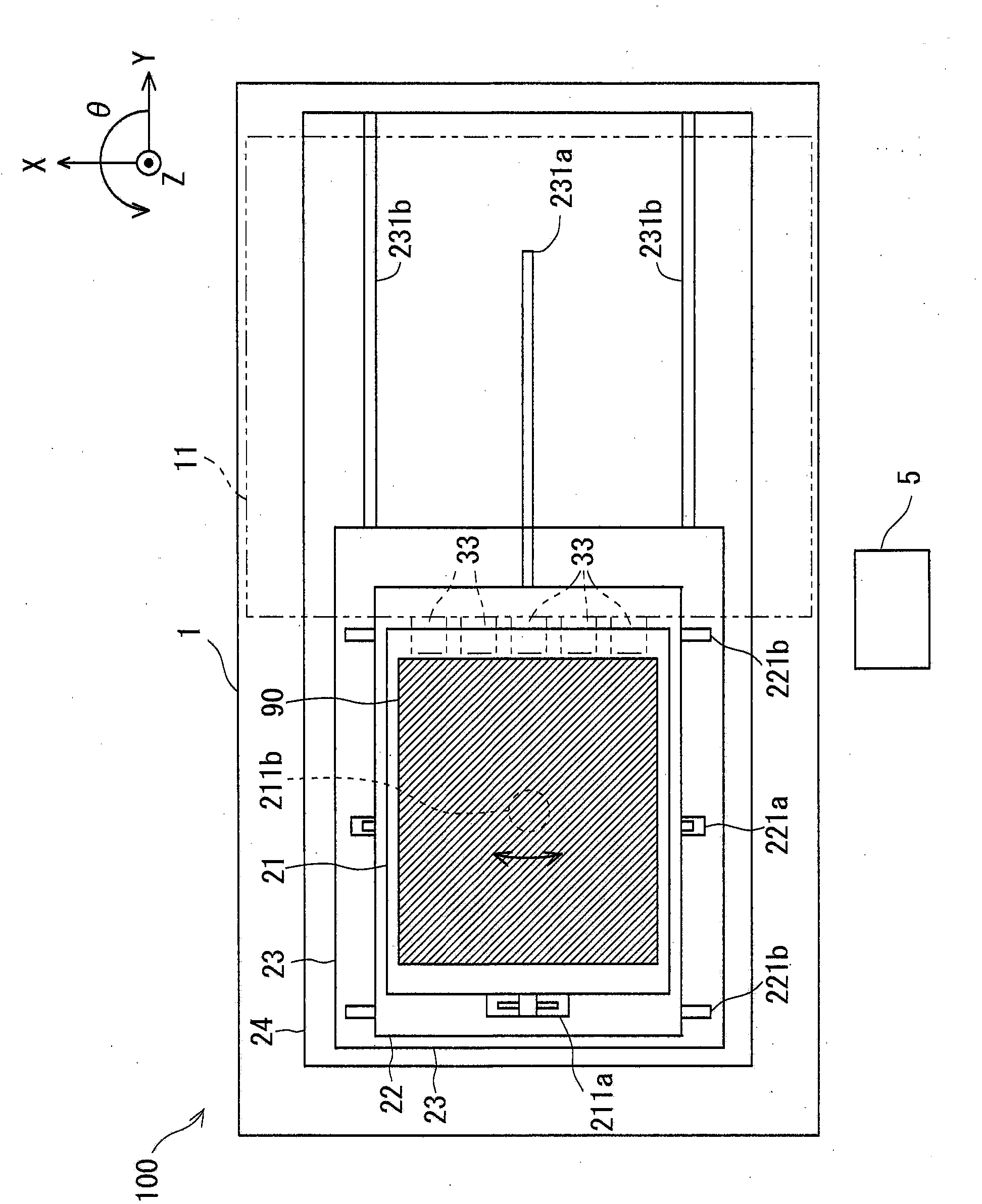
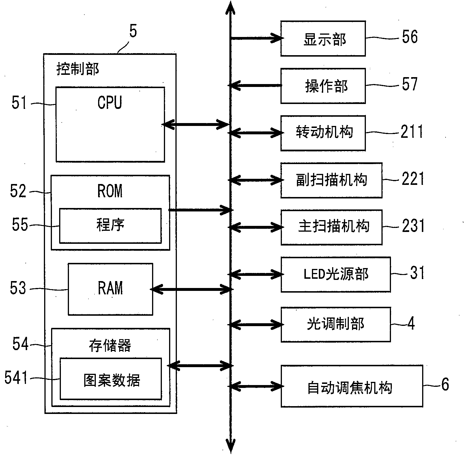
[0070] figure 1 It is a perspective view showing an overview of the drawing device 100 of the embodiment. In addition, figure 2 It is a plan view showing an overview of the drawing device 100. and, image 3 It is a bus wiring diagram of the drawing device 100. in figure 1 Here, for the convenience of illustration and description, the Z-axis direction is defined as the vertical direction, and the XY plane is the horizontal plane. However, this is defined to facilitate understanding of the positional relationship and does not limit the directions described below. The same applies to the following figures. In addition, in figure 2 Here, for convenience of description, the bridge structure 11 and the optical head 33 are indicated ...


PUM


Abstract

The invention provides a technique which improves drawing precision of a pattern of a belt-shaped area at an end of a substrate. A drawing device (100) draws the pattern on the substrate (90) through irradiating strip-shaped drawing light to the substrate on which a photoreceptor is formed. The drawing device is provided with the components of: a plurality of optical heads (33a-33e) which irradiates the drawing light; a secondary scanning mechanism (221) which makes the optical heads (33a-33e) move relative to the substrate in an auxiliary scanning direction (+x direction); and a main scanning mechanism which make the optical heads move relative to the substrate in a main scanning direction (+y,-y direction). Additionally, the drawing device is provided with an automatic focusing mechanism (6) which adjusts the focus position of the drawing light that is radiated from the plurality of optical heads. The automatic focusing mechanism for partial optical heads (33b-33e) in the plurality of optical heads takes a position which offsets from the central position of the drawing light to the auxiliary scanning direction on the substrate as a detecting position for detecting separating distance variation.

Description

technical field [0001] The present invention relates to a semiconductor substrate, a printed circuit board, a substrate for a color filter included in a liquid crystal display device, a glass substrate for a flat panel display, a substrate for a magnetic disk, etc. A technique for drawing a pattern on a substrate by irradiating light to various substrates such as substrates for optical discs and panels for solar cells (hereinafter, simply referred to as "substrates"). Background technique [0002] There is known an exposure device (so-called drawing device) that, when exposing a pattern of a circuit or the like on a photosensitive material coated on a substrate, does not use a mask or the like, but uses a pattern modulated according to data on which the pattern is recorded. Light (drawing light) scans the photosensitive material on the substrate, thereby directly exposing a pattern on the photosensitive material. For example, a drawing device is known in which a drawing lig...

Claims


Application Information

Patent Timeline
IPC IPC(8): G03F7/207
CPCG03F7/20G03F7/26H01L21/027
Inventor 城田浩行重本宪永井妥由
Owner DAINIPPON SCREEN MTG CO LTD
Why Eureka
Try Eureka