

Camera rotating structure
A technology of rotating structure and camera
- Summary
- Abstract
- Description
- Claims
- Application Information
AI Technical Summary
Problems solved by technology
Method used
Image

Examples
Embodiment Construction
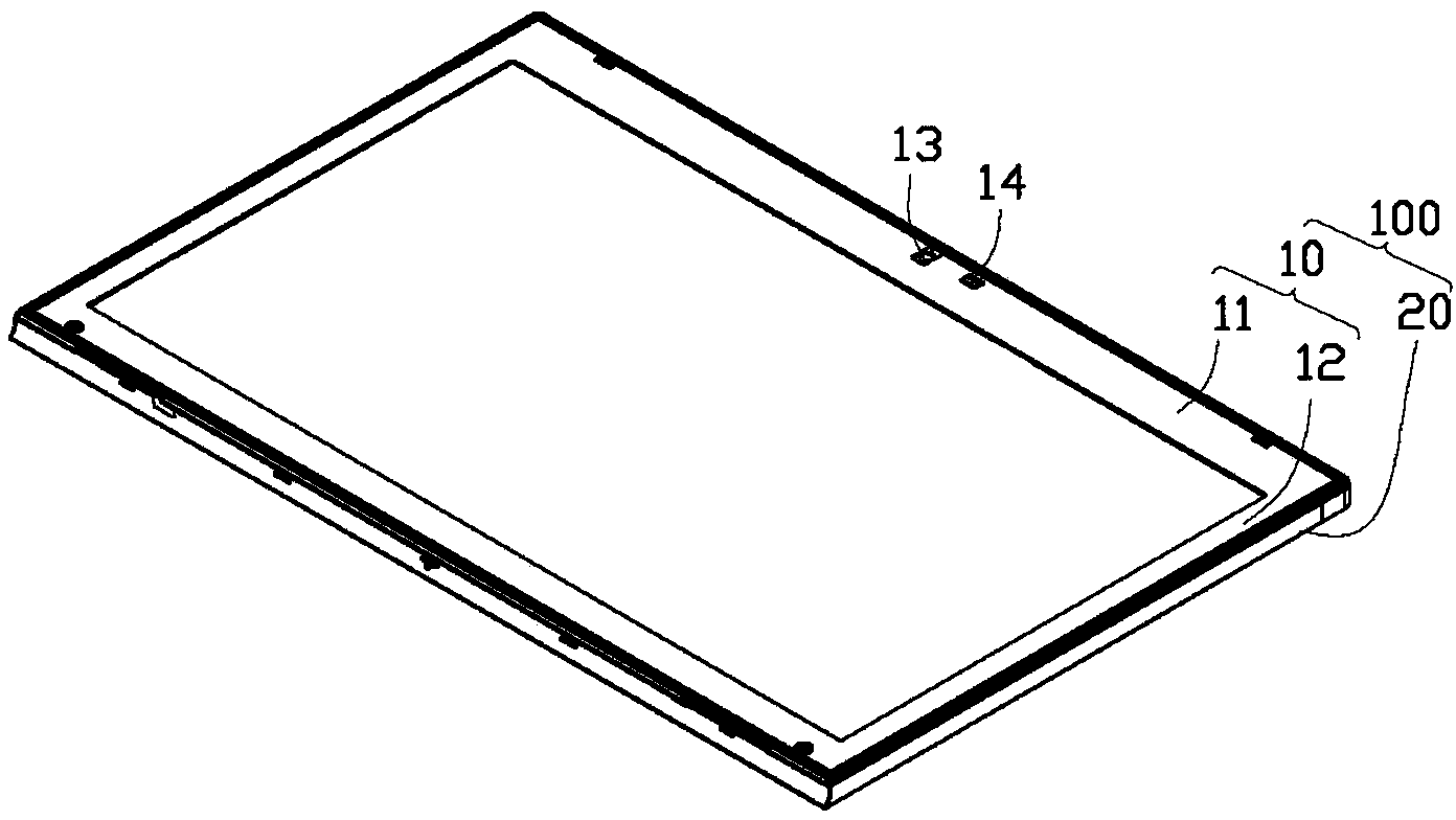
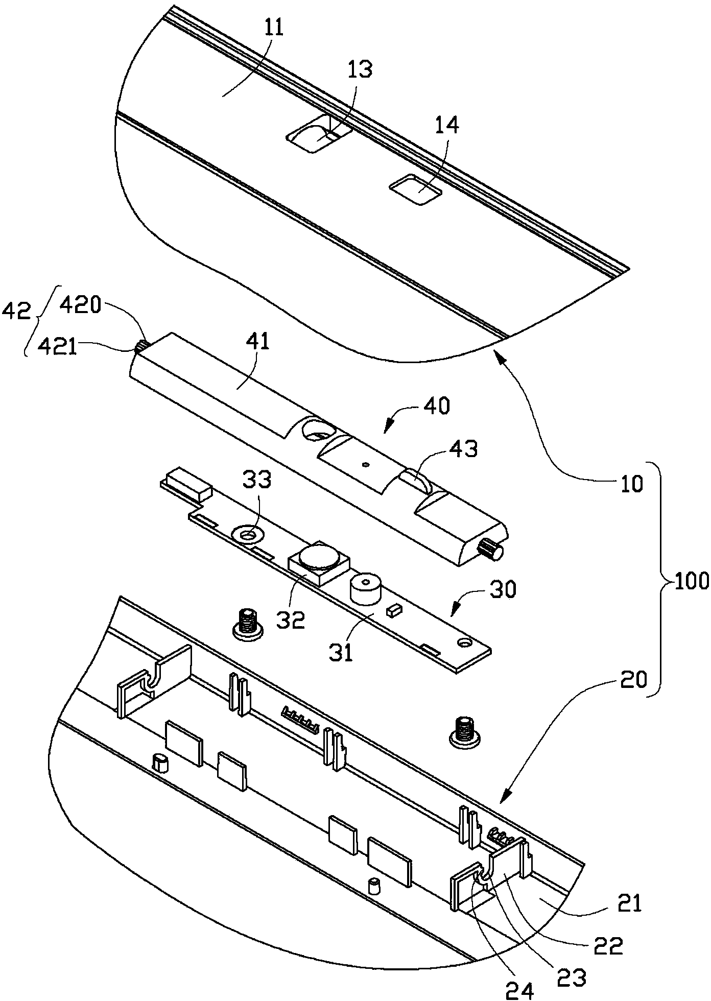
[0022] see figure 1 and figure 2 A preferred embodiment of the camera rotation structure of the present invention includes a housing 100 for installing a display screen (not shown) of an electronic device, a camera device 30 for installing a camera of an electronic device, and a The rotating part 40 connected to the camera device 30 , the casing 100 includes a top casing 10 for installing the display screen of the electronic device and a bottom casing 20 for installing the display screen of the electronic device.
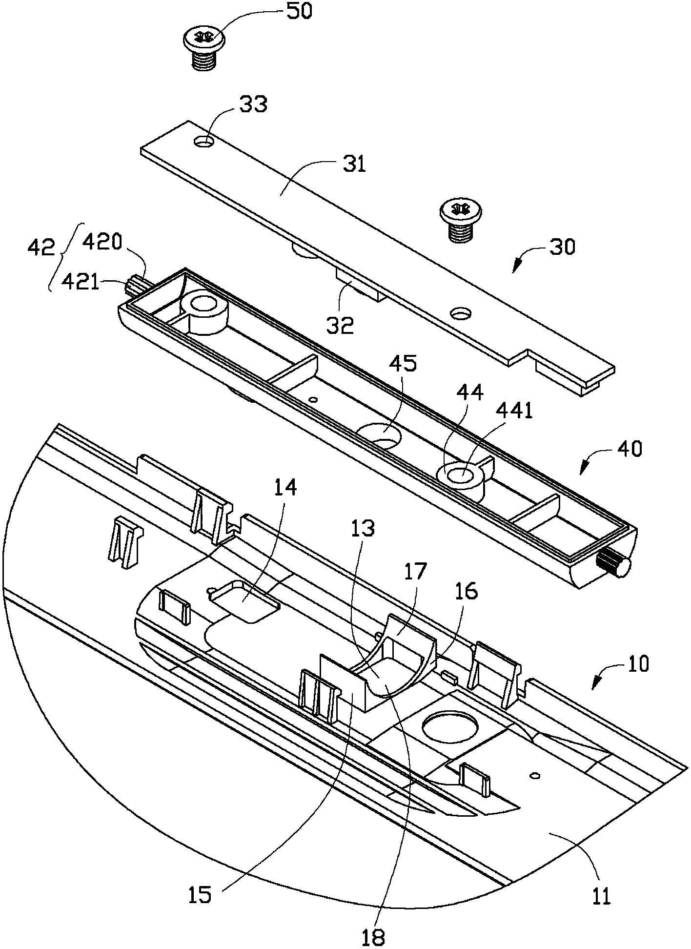
[0023] see figure 2 and image 3 , the top case 10 includes a top case body 11 and a resisting portion 12 extending from the top case body 11 . The top shell body 11 defines a first opening 13 and a second opening 14 . The abutment portion 12 includes two first side surfaces 15 extending vertically from the top shell body 11, two second side surfaces 16 connecting the two first side surfaces 15, one with the first side surfaces 15 and The concave surface 17 c...
PUM
 Abstract
Description
Claims
Application Information