Electromagnetic operating mechanism

A technology of electromagnetic operation and electromagnetic mechanism, applied in the direction of protection switch operation/release mechanism, etc., can solve the problems of poor breaking capacity and slow breaking speed, and achieve the effect of strong breaking capacity and fast breaking speed

Inactive Publication Date: 2014-10-01
JAECELE ELECTRIC
View PDF4 Cites 4 Cited by
  • Summary
  • Abstract
  • Description
  • Claims
  • Application Information

AI Technical Summary

Problems solved by technology

[0007] Therefore, the technical problem to be solved by the present invention lies in the problems of slow breaking speed and poor breaking capacity of the electric operating mechanism for circuit breakers dedicated to smart meters in the prior art, thereby providing an electromagnetic operating mechanism with fast breaking speed and strong breaking capacity

Method used


Image

  • Electromagnetic operating mechanism
  • Electromagnetic operating mechanism
  • Electromagnetic operating mechanism

Examples


Embodiment 1

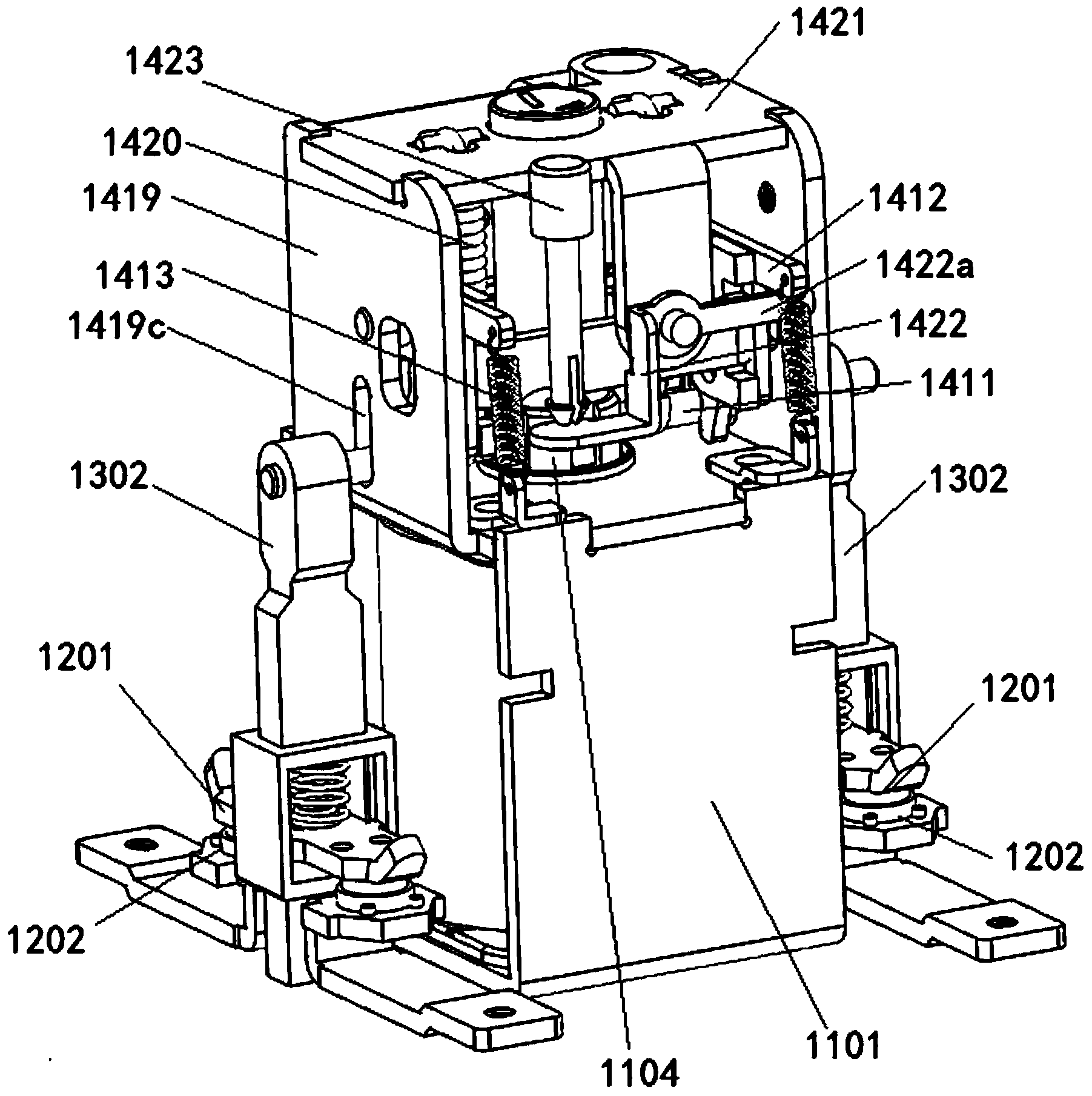
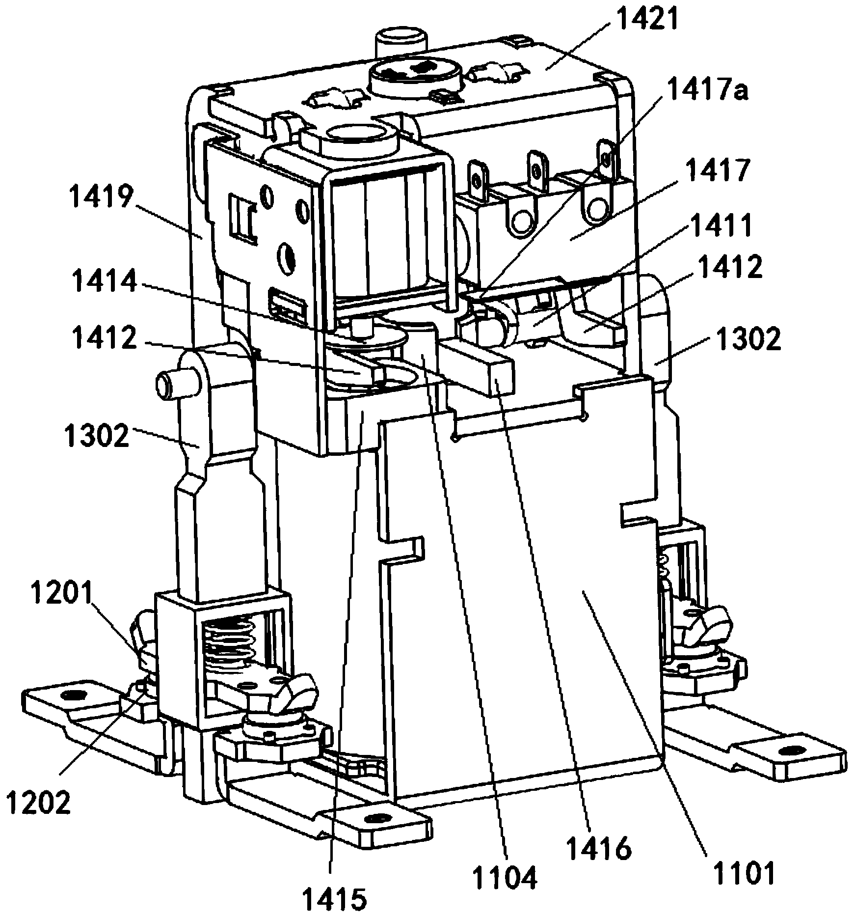
[0067] like Figure 1-2 Shown is the preferred embodiment of the electromagnetic operating mechanism of the present invention. The electromagnetic operating mechanism is mainly used in a special circuit breaker for smart meters, and includes an electromagnetic mechanism.

[0068] like figure 1 and Figure 10 As shown, the electromagnetic mechanism includes an electromagnet 11, and the electromagnet includes a housing 1101, a coil 1103 fixed in the housing 1101, and a static iron core 1102, and is arranged on the coil 1103 so as to reciprocate and move linearly. The moving iron core 1102 inside, the moving iron core 1102 has an initial position before the coil 1103 is energized and moves from the initial position to the static iron core 1102 under the action of electromagnetic attraction generated at the moment when the coil 1103 is energized the pull-in position; the reaction force spring 1420 is applied to the axial reaction force of the moving iron core 1102, and the movi...

Embodiment 2

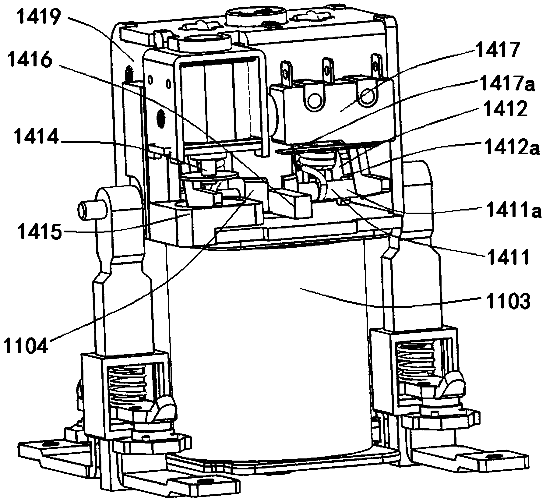
[0088] As an alternative structure of the reset member 1415 in the energy-saving mechanism in Embodiment 1, in this embodiment, the reset member 1415 is the first triggered part 1412b of the locking member 1412, and the first triggered part After the tripping end 1414 is triggered, the triggering part 1412 b pushes the tripping end 1414 back to the return position under the action of the biasing force of the biasing member 1403 . In this embodiment, the structure and working method of the first triggered part 1412b and the biasing part 1403 are fully utilized, and the first triggered part 1412b is used as a reset part, when the tripping end of the tripping unit After triggering the first triggered part 1412b so that the first triggered part 1412b rotates at a small angle in the triggering direction, the first triggered part 1412b rotates in the opposite direction again under the biasing force of the biasing member , so as to push the tripping end 1414 back to its return positi...


PUM


Abstract

An electromagnetic operating mechanism is applied to a special circuit interrupter of an intelligent electric meter, and comprises an electromagnetic mechanism and an energy-saving mechanism, wherein the electromagnetic mechanism comprises an electromagnet, a reactive spring and a transmission mechanism; the energy-saving mechanism comprises a lock catch unit, an energy-saving unit and a tripping unit; a movable iron core of the electromagnet is moved to an attracting position at the coil electrifying moment; the fastening unit and the movable iron core form a lock catch structure to enable the movable iron core to be fixed at the attracting position, in addition, the energy-saving unit controls the power off of the coil at the moment when the movable iron core leaves an initial position, so that the power consumption of the electromagnetic mechanism is zero, and a large amount of electric energy is saved; the tripping unit can receive a tripping command and then triggers the lock catch unit to unlock the lock catch structure, as a result, the movable iron core quickly returns to the initial position, and after tripping, the stripping unit can reset for reuse.

Description

technical field [0001] The invention relates to an electromagnetic operating mechanism, which can be used in a special circuit breaker for an intelligent electric meter, and belongs to the technical field of low-voltage electric appliance accessories. Background technique [0002] The smart meter is the smart terminal of the smart grid. It is no longer a meter in the traditional sense. In addition to the basic power consumption measurement function of the traditional meter, the smart meter also has two-way multiple tariffs in order to adapt to the use of smart grid and new energy. Intelligent functions such as metering function, user terminal control function, two-way data communication function of multiple data transmission modes, and anti-theft function, smart meters represent the development direction of future energy-saving smart grid end-user intelligent terminals. [0003] Smart meters are often used in conjunction with special circuit breakers. At present, the commonl...

Claims


Application Information

Patent Timeline
IPC IPC(8): H01H71/10H01H71/24
Inventor 彭全昌刘永华
Owner JAECELE ELECTRIC
Why Eureka
Try Eureka