Vehicle control apparatus, and method of controlling railroad hybrid vehicle
A vehicle control device and vehicle drive technology, which can be applied to the layout of multiple different prime movers of hybrid vehicles and general power plants, and engine-driven traction. It can solve the problems of engine starting failure and time-consuming, and achieve smooth And the effect of reliable starting
Active Publication Date: 2014-10-01
MITSUBISHI ELECTRIC CORP
7 Cites 2 Cited by
AI-Extracted Technical Summary
Problems solved by technology
[0008] However, according to the prior art described above, the generator torque and the engine torque interfere with each other, and ...
Method used
[0051] Utilizing the above structural elements, the system controller 8 controls the engine 1 through the engine controller 7 and controls the generator 2 through the rectifier controller 9 according to the state of the battery 5 and the start signal from the cab 6. With the above control, when the engine is started, it can be started up to the idle speed ωe_idol smoothly and reliably.
[0062] As described above, according to the vehicle control device and the control method for a railroad hybrid vehicle according to Embodiment 1, the rotation speed threshold value at the time of forcibly performing the control of turning off the power to the generator is set to the fuel injection Between the engine speed command value at the start command and the engine idle speed, the energization of the generator can be controlled to be turned off before the engine speed reaches the idle speed, so that the engine using the generator can be started smoothly and reliably.
[0...
Abstract
A vehicle control apparatus is provided with a system controller for centrally controlling an engine controller and a converter controller. The system controller causes, via the converter controller, a generator to be driven in accordance with a generator rotational speed command value ([omega]c_ref1) smaller than an idling-maintaining minimum rotational speed ([omega]e_idol_min) for the engine; initiates, via the engine controller, fuel injection into the engine after the elapse of a predetermined time; and outputs a gate cutoff signal (GSTOP) for turning off energization of the generator to a converter when the rotational speed of the engine becomes greater than the generator rotational speed command value ([omega]c_ref) and reaches a predetermined rotational speed threshold value ([omega]e_th) smaller than the idling-maintaining minimum rotational speed ([omega]e_idol_min).
Application Domain
Gas pressure propulsion mountingPropulsion using engine-driven generators +4
Technology Topic
Hybrid vehicleFuel injection +7
Image
Examples
- Experimental program(3)
Example Embodiment
[0026] Implementation mode 1.
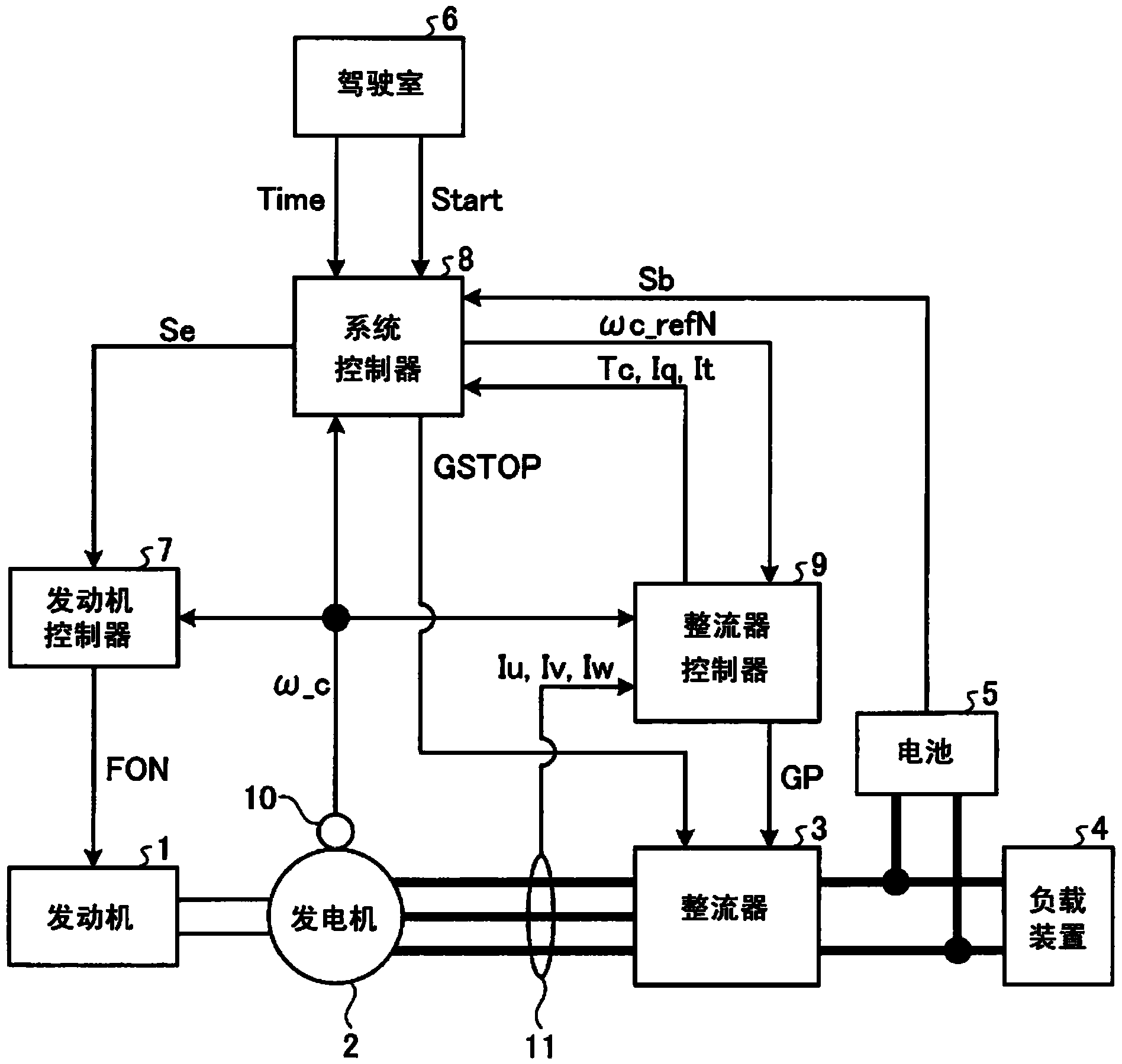
[0027] figure 1 It is a diagram showing a configuration example of a vehicle drive system including the vehicle control device according to Embodiment 1 of the present invention, and shows a configuration when applied to a series hybrid type engine system. like figure 1 As shown, the vehicle drive system involved in Embodiment 1 adopts the following structure, that is, includes: an engine 1; a generator 2 driven by the engine 1 and outputting alternating current; a rectifier 3 that converts alternating current into a desired direct current; and the rectifier 3 Load device 4 and battery 5 for electrical connection; driver's cab 6 for vehicle control; engine controller 7 for controlling engine 1; system controller for controlling engine controller 7 and rectifier controller 9 described later 8; a rectifier controller 9 for adjusting the power of the load device 4 and the battery 5; and a rotation speed detector 10 and a current sensor 11 as sensors.
[0028] Next, refer to Figure 1 to Figure 5 Detailed description of each drawing figure 1 Functions of the components shown.
[0029] First, the output shaft of the engine 1 and the rotor shaft of the generator 2 are mechanically coupled by a coupling portion (not shown). Therefore, the rotation speed of the engine 1 (engine rotation speed) and the rotation speed of the generator 2 (generator rotation speed) match. Engine 1 generates torque around a shaft (shaft torque) based on a fuel injection command FON from engine control unit 7 . The generator 2 is, for example, a three-phase alternator, and uses the driving force of the engine 1 to rotate and generate electricity. On the other hand, the generator 2 can also operate as an engine. For example, when the engine 1 is started, electric power can be consumed by cranking the engine 1 or rotating the engine 1 using the driving force of the generator 2 .
[0030] The rectifier 3 is composed of a plurality of switching elements and rectifying elements not shown. To this rectifier 3, when the generator 2 operates as a generator, the three-phase alternating current output from the generator 2 is input, and based on the gate signal GP from the rectifier controller 9, the input three-phase alternating current is converted into a desired DC power is supplied to either one or both of the load device 4 and the battery 5 . On the other hand, when the generator 2 operates as a motor, the rectifier 3 converts the DC power output from the battery 5 into a desired three-phase AC power based on the gate signal GP from the rectifier controller 9 to drive the generator 2 . However, when the gate-off signal GSTOP from the system controller 8 is input, the power conversion operation is stopped regardless of the presence or absence of the gate signal GP. Accordingly, the drive of the generator 2 can be stopped by the gate-off signal GSTOP from the system control unit 8 .
[0031] The load device 4 is electrically connected to the rectifier 3 and operates by receiving the direct current supplied from the rectifier 3 . In addition, although the components of the load device 4 are not shown in the figure, for example, an inverter device for converting DC power into AC power, a motor for outputting driving force for accelerating a railway vehicle, etc., decelerates the output of the motor and transmits it to the wheel shaft. The reducer and other components.
[0032] Battery 5 is, for example, a lithium-ion rechargeable battery, and stores DC power supplied from rectifier 3 or regenerative power from load device 4 . On the other hand, battery 5 drives generator 2 and load device 4 using the stored power. The battery 5 may have any configuration as long as it has the function of storing (charging) and discharging direct current.
[0033] The cab 6 is an operating device for the driver to control the vehicle as described above, and generates and outputs a vehicle start signal Start to the system controller 8 described later when the engine is started. In addition, at this time, the cab 6 sets the time when the vehicle start signal Start is issued as 0 seconds, records at regular intervals, generates the recorded information as an elapsed time Time, and sends it to the system controller 8 .
[0034] The engine controller 7 is a control unit that controls the engine 1 as described above. like figure 2 As shown, a fuel injection characteristic MAP corresponding to the rotational speed of the engine 1 is provided in the engine controller 7 . Engine controller 7 drives engine 1 by referring to fuel injection command FON corresponding to engine rotation speed ω_c detected by rotation speed detector 10 from fuel injection characteristic MAP based on engine start signal Se from system controller 8 .
[0035] The system controller 8 collectively controls the engine controller 7 , the rectifier controller 9 and the rectifier 3 to supply power to the load resistor 4 and the battery 5 and to start the engine 1 .
[0036] The rotational speed detector 10 detects the rotational speed ω_c of the generator 2 and outputs the rotational speed ω_c which is a detection signal to the engine controller 7 , the system controller 8 , and the rectifier controller 9 . The current sensor 11 is connected between the three-phase lines of the generator 2 and the rectifier 3 , detects the current Iu, Iv, and Iw of each phase, and outputs it to the rectifier controller 9 . In addition, in figure 1 In , all phase currents Iu, Iv, and Iw are detected, but it is not necessary to detect all currents Iu, Iv, and Iw, as long as any two of them are detected.
[0037] Next, specific control contents of the vehicle control device according to Embodiment 1 will be described. First, the system controller 8 such as image 3 As shown, a start determination unit 12 , a generator speed command value MAP13 , comparators 14 to 16 , and a regenerative torque determination unit 17 are included. The state of charge Sb of the battery 5 and the vehicle start signal Start from the cab 6 are input to the start determination unit 12 , based on the state of charge Sb and the vehicle start signal Start, it is determined whether the engine 1 can be started, and an engine start signal Sk is output. For example, when the state of charge Sb of the battery is not abnormal and the vehicle start signal Start is on, the engine start signal Sk indicating "on" is output to the generator rotational speed command value MAP13.
[0038] Here, in the generator rotation speed command value MAP13 as Figure 4As shown, there is a predetermined generator rotation speed command value ωc_refN so that the predetermined generator rotation speed command corresponding to the elapsed time Time sent from the cab 6 and the engine start signal Sk sent from the start determination unit 12 is output. Value ωc_refN. The generator rotational speed command value ωc_refN is set within a range smaller than the idle rotational speed ωe_idol of the engine 1 .
[0039] In addition, the generator rotational speed command value ωc_refN is set to a value that gradually increases (N is not a natural number starting from 0). For example, when the idling speed of the engine is about 650 rpm, values such as ωc_ref0 = 0 rpm, ωc_ref1 = 450 rpm, ωc_ref2 = 500 rpm, etc. are set.
[0040] Also, the generator rotation speed command value ωc_refN is set to become the generator rotation speed command value ωc_ref(N+1) such that the generator rotation speed command value ωc_ref(N+1) reaches the generator rotation speed command value ωc_ref(N+1) after a certain time interval tN, for example. In addition, for the setting of the time interval tN, in addition to the above description, it can also be considered that a certain conversion rate θN is set between the generator speed command value ωc_refN and the generator speed command value ωc_ref(N+1). method, but any method can be used to prevent the rapid generator speed ω_c. In addition, when the natural number N is 1 or 2, the same setting method can be applied.
[0041] Then, the generator rotation speed command value ωc_refN is set so that the generator rotation speed command value ωc_ref(N+1) is maintained for a period of TN seconds after reaching the generator rotation speed command value ωc_ref(N+1). When the natural number N is 1 or 2, the generator speed command value ωc_refN is gradually raised back to the generator speed command value ωc_refN while maintaining the time interval TN, and waits for the timing when the engine controller 7 starts the fuel injection command FON.
[0042] In addition, the generator rotation speed command value MAP13 sequentially stores the elapsed time Time sent from the cab 6 in the internal memory, and when the stored elapsed time Time exceeds the period upper limit value Tmax, it is determined that the engine 1 has failed, and the grid is turned off. The ON signal GSTOP is output to the rectifier 3 .
[0043] return image 3 , in the comparator 14, the generator speed command value ωc_refN sent by the generator speed command value MAP13 is compared with the generator speed ω_c sent by the rotation speed detector 10, and when the generator speed command value ωc_refN is greater than the generator speed ω_c In the case of , the engine start signal Se is output to the engine controller 7 .
[0044] In the comparator 15, the generator rotation speed ω_c sent from the rotation speed detector 10 is compared with the generator grid-off rotation speed ωc_GSTOP sent from the comparator 16 described later. When the opening rotation speed ωc_GSTOP matches, the gate-off signal GSTOP is output to the rectifier 3 .
[0045] In the comparator 16 , the minimum idling speed ωe_idol_min of the engine 1 is compared with the engine speed threshold ωe_th, and a smaller value is output to the comparator 15 . Here, the minimum idling maintenance rotational speed ωe_idol_min is a rotational speed that can be autonomously rotated in consideration of the operating state of the engine 1 and the variation in engine characteristics in the standby state, and the rotational speed information is sequentially stored in the system controller 8 . The engine speed threshold ωe_th is the speed between the generator speed command value ωc_refN of the engine 1 and the minimum idle speed maintenance speed ωe_idol_min. For example, when the idle speed maintenance speed of the engine 1 is 600rpm and ωc_refN=450rpm, the engine speed threshold ωe_th is set to 550rpm Wait.
[0046] The regenerative torque determination unit 17 determines whether the generator 2 is performing a regenerative operation based on any state quantity among the torque sub-current It, the q-axis current Iq, the torque estimated value Tc, etc. from the rectifier control unit 9, and outputs a grid Disconnect signal GSTOP. For example, when the sign of the estimated torque value Tc is negative, it is determined that the generator 2 is regenerative, and the gate-off signal GSTOP is output.
[0047] In addition, the structure of the rectifier controller 9 is as Figure 5 shown. like Figure 5 As shown, the rectifier controller 9 has a structure including a voltage controller 18 , a lower limit torque limiter 19 , and a speed PI controller 20 .
[0048] The rectifier control unit 9 calculates difference information Δω between the generator rotation speed command value ωc_refN sent from the system control unit 8 and the generator rotation speed ω_c obtained from the rotation shaft of the generator 2 . Thereafter, the speed PI controller 20 performs proportional-integral to Δω based on a gain set according to a desired speed control response in advance, and outputs the calculation result as a generator torque command value Tc_ref1. The generator torque command value Tc_ref1 is subjected to lower limit limit processing by the lower limit torque limiter 19 and is output to the voltage controller 18 as a generator torque command value Tc_ref2.
[0049] The voltage controller 18 performs so-called torque control to make the output torque of the generator 2 follow the generator torque command value Tc_ref2, and adjusts the voltage command output to the rectifier 3, and the internal voltage of the voltage controller 18 corresponding to the voltage command PWM operation to generate and output the gate signal GP to drive the rectifier 3 . In addition, the output torque of the generator 2 is controlled by driving the rectifier 3 .
[0050] The voltage controller 18 sends to the system control unit 8 information such as the torque sub-current It, the q-axis current Iq (or any one of them), or the torque estimated value Tc. The phase currents Iu, Iv, Iw are obtained during vector control of at least two currents. In addition, various well-known methods can be used for the vector control of the voltage controller 18, and therefore, detailed description thereof will be omitted here. In addition, the control of the system controller 8 is as described above.
[0051] Using the above components, the system controller 8 controls the engine 1 through the engine controller 7 and controls the generator 2 through the rectifier controller 9 according to the state of the battery 5 and a start signal from the cab 6 . With the above control, when the engine is started, it can be started up to the idle speed ωe_idol smoothly and reliably.
[0052] The vehicle control device according to Embodiment 1 has the above-mentioned functions, and therefore can be executed by the first to fourth starting methods and the like described below.
[0053] (the first start method)
[0054] Image 6 It is a diagram for explaining the first starting method of the vehicle control device according to Embodiment 1. The horizontal axis represents time, and the vertical axis represents engine rotation speed, engine torque, and generator speed control intervals from top to bottom. In addition, in figure 1 In this case, the generator speed command values ωc_ref1 to N are output from the system controller 8 to the rectifier controller 9, but during the period before the engine controller 7 controls the engine, specifically, before the fuel injection command FON is output Inside, engine speed as shown in 6 vs. Figure 4 The indicated generator rotational speed command value ωc_ref1 is the same value. On the other hand, when the engine 1 rotates with its own driving force established by its own fuel injection, the engine 1 accelerates to an idle speed ωe_idol which is a rotational speed higher than the generator rotational speed command value ωc_ref1 by its own driving force. In the controller 9 , the generator torque command value Tc_ref1 is reduced by the action of the speed PI controller 20 .
[0055] return Image 6 , in the first starting method, the rotational speed threshold ωe_th is set between the generator rotational speed command value ωc_ref1 and the idle maintenance minimum rotational speed ωe_idol_min. When the engine start command, that is, the vehicle start signal Start, is output from the cab 6 to the system controller 8, the rectifier controller 9 controls the generator 2 according to the signal from the system controller 8, and controls the power of the generator 2 and the engine 1. Rotating speed. The engine speed follows the generator speed command value ωc_ref1, and for the generator torque, a torque value corresponding to the generator speed command value ωc_ref1 is output. When fuel injection to the engine 1 is started, the engine speed rises rapidly beyond the generator speed command value ωc_ref1, and when it reaches the speed threshold ωe_th, the gate-off signal GSTOP is output, and the engine continues to rotate autonomously while maintaining the idle speed ωe_idol . When this control is performed, the action of the speed PI controller 20 based on the difference information between the generator rotation speed command value ωc_ref1 and the generator rotation speed ω_c causes the generator torque to decrease from a certain value toward zero as shown in the figure. And it will be reduced to a negative value that generates regenerative torque, but before the rotational speed threshold value ωe_th is exceeded, the gate-off signal GSTOP is output and the drive of generator 2 is stopped. Therefore, the area of the portion where regenerative torque is generated (Fig. The portion of K1 shown) becomes very small. Thereby, when the engine is started, there is almost no mutual interference between the generator torque and the engine torque, so the engine can be started smoothly and reach the idle speed ωe_idol. In addition, since the interference between the generator torque and the engine torque can be reduced, starting of the engine can be performed smoothly and reliably.
[0056] (Second activation method)
[0057] Figure 7 It is a figure explaining the 2nd activation method of the vehicle control apparatus of Embodiment 1. in the Figure 7 In the second starting method shown, the generator rotational speed command value is provided in multiple stages, and is gradually increased at every time interval T. Specifically, in Figure 7 In the example, after the generator speed command value is set to ωc_ref1, the generator speed command value is increased to ωc_ref2 after a time interval T1, and the fuel injection command FON is output when the generator speed command value is ωc_ref2. With this control, for example, when the engine 1 is in a cold state, even if the engine 1 cannot be started at the generator rotation speed command value ωc_ref1 because the lubrication state of the engine 1 is poor, the generator rotation speed command value can be increased to ωc_ref2 to start starting the engine. 1. That is, even when the starting characteristics of the engine 1 vary depending on the ambient temperature, there is an effect of increasing the reliability of starting.
[0058] (the third activation method)
[0059] Figure 8 It is a figure explaining the 3rd activation method of the vehicle control apparatus of Embodiment 1. Should Figure 8 In the third starting method shown, the period upper limit value Tmax is set in the rotation speed control of the generator 2 . Specifically, in Figure 8 In this example, when the engine fuel injection command FON has not been established and the engine speed has not risen to the idle speed ωe_idol even though the period upper limit value Tmax has been exceeded, the gate-off signal GSTOP is output to cut off the energization of the generator 2 . With this control, it is possible to determine a failure or a problem of the engine 1, and it is possible to protect the engine 1 from an abnormal rotation state.
[0060] (the fourth starting method)
[0061] Figure 9 It is a figure explaining the 4th activation method of the vehicle control apparatus of Embodiment 1. In this fourth starting method, when the rotation speed control of the generator 2 is performed, the lower limit torque limiter 19 provided in the rectifier controller 9 (refer to Figure 5 ) limits such as Figure 9 Set to zero as indicated by the dashed-two dotted line on the time axis of , to suppress the regenerative action. With this control, since the generator torque does not fall below zero, the engine 1 can be started without generating the regenerative torque of the shaded area of K2, so that engine stall (so-called parking) can be prevented and smooth And reliably switch to the idling state of the engine 1 .
[0062] As described above, according to the vehicle control device and the control method of the railroad hybrid vehicle according to Embodiment 1, the rotation speed threshold value at the time of forcibly performing the control of turning off the power to the generator is set at the time when the fuel injection start command is issued. Therefore, the engine using the generator can be started smoothly and reliably.
[0063] In addition, according to the vehicle control device and the control method of the railway hybrid vehicle according to Embodiment 1, the generator rotation speed command value is set in multiple stages, and the power generation set in the multiple stages is sequentially selected at regular time intervals from small to large. Therefore, even when the starting characteristic of the engine 1 side changes depending on the ambient temperature, the reliability of starting can be increased.
[0064] In addition, according to the vehicle control device and the control method for a railway hybrid vehicle according to the first embodiment, a predetermined period upper limit value is set, and when the upper limit value of the period is exceeded but the fuel injection of the engine has not been established and the engine speed has not yet When the rotation speed is increased to the idling maintenance speed, the energization of the generator is controlled to be turned off, so that failure and problems of the engine can be determined, and the engine can be protected from the abnormal rotation state.
[0065] In addition, according to the vehicle control device and the control method of the railway hybrid vehicle according to Embodiment 1, the lower limit torque limiter is provided on the input side of the rectifier controller, and the regenerative operation at the time of starting the engine is suppressed, so that the engine can be prevented from stalling. And it can smoothly and reliably switch to the idling state of the engine 1 .
Example Embodiment
[0066] Implementation mode 2.
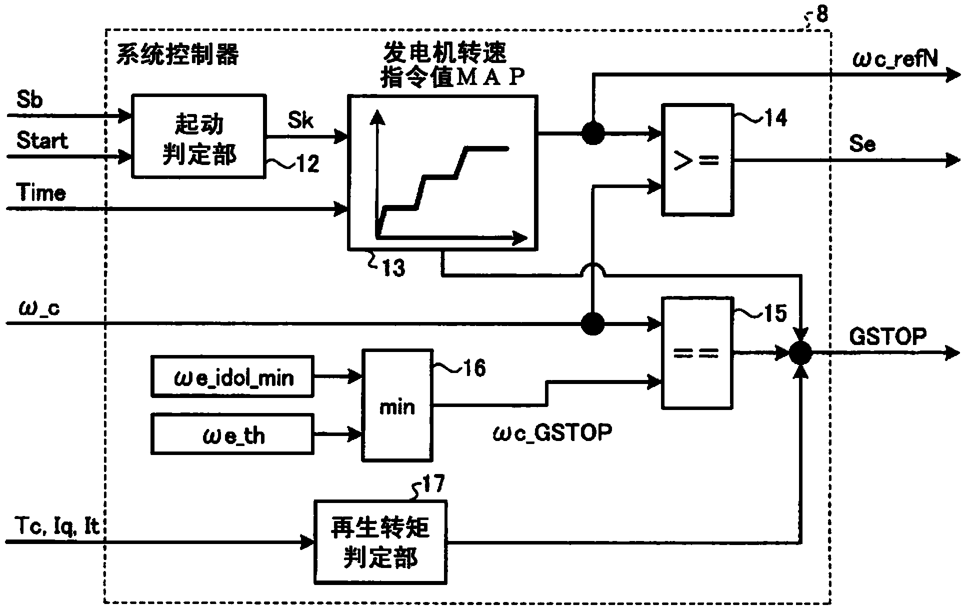
[0067] Figure 10 It is a figure explaining the activation method (fifth activation method) concerning Embodiment 2. Comparing the fifth starting method with the fourth starting method according to Embodiment 1, the difference lies in the timing at which the gate-off signal GSTOP is transmitted from the system controller 8 to the rectifier 3 . The voltage controller 18 that is arranged on the rectifier controller 9 (referring to Figure 5 )use figure 1 At least two of the phase currents Iu, Iv, and Iw detected by the current sensor 11 generate a gate signal GP for controlling the rectifier 3 . The control performed by the voltage controller 18 is referred to as vector control, but when this vector control is performed, the vector divided current It is recognized. Therefore, power running/regeneration can be judged from the sign of the torque sub-current It. Additionally, the function as image 3 As shown, it is executed by the regenerative torque determination unit 17 provided in the system controller 8 . The regenerative torque judging section 17 judges power running/regeneration according to the sign of the torque sub-current It, and generates a grid disconnection signal GSTOP at the moment when the generator vector is switched to the regenerative vector and outputs it to the rectifier 3, disconnecting the generator 2 power on. With this control, the engine 1 can be started without generating the regenerative torque of the shaded area K3, so that the engine can be prevented from stalling (so-called parking), and the engine 1 can be smoothly and reliably shifted to an idling state.
Example Embodiment
[0068] Implementation mode 3.
[0069] Figure 11 It is a figure explaining the activation method (sixth activation method) concerning Embodiment 3. Comparing the sixth starting method with the fifth starting method according to Embodiment 2, the difference lies in the detecting means for detecting regenerative torque. More specifically, in Embodiment 3, the torque detector 21 is provided on the shaft connecting the engine 1 and the generator 2 , and the value of the generator axis torque Tck is detected from the torque detector 21 . This generator axis torque Tck is sent to the regenerative torque determination unit 17 of the system controller 8 , and the regenerative torque determination unit 17 determines the presence or absence of a regenerative operation. Note that subsequent operations are the same as those in Embodiment 2 described above, and thus detailed description thereof will be omitted.
[0070] According to the sixth starting method, when the engine 1 is started using the generator 2, it is determined based on the generator axis torque Tck detected by the torque detector 21 whether or not the generator 2 is being regeneratively operated. In the case of regenerative operation, the gate-off signal GSTOP is generated and output to the rectifier 3, and the energization to the generator 2 is controlled to be turned off. Therefore, it is possible to prevent the engine from stalling, and it is possible to smoothly and reliably switch to the idle speed of the engine 1 state.
PUM


Description & Claims & Application Information
We can also present the details of the Description, Claims and Application information to help users get a comprehensive understanding of the technical details of the patent, such as background art, summary of invention, brief description of drawings, description of embodiments, and other original content. On the other hand, users can also determine the specific scope of protection of the technology through the list of claims; as well as understand the changes in the life cycle of the technology with the presentation of the patent timeline. Login to view more.