Soundproof cover for charged-particle beam device, and charged-particle beam device
A technology of charged particle wires and charged particles, which is applied in the direction of circuits, discharge tubes, electrical components, etc., can solve problems such as hindering the dust resistance of clean rooms
- Summary
- Abstract
- Description
- Claims
- Application Information
AI Technical Summary
Problems solved by technology
Method used
Image

Examples
Embodiment 1
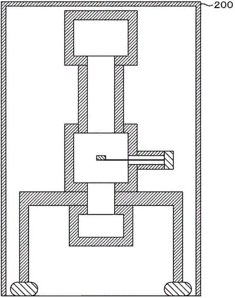
[0049] In this example, use Image 6 and even Figure 7 An example of a soundproof enclosure structure capable of effectively reducing standing sound waves in the enclosure and a charged particle beam device having this structure will be described.
[0050] Image 6 is an example of a cross-sectional view of the charged particle beam device of this embodiment and its soundproof cover, in which the perspective view of the part indicated by the dotted line is represented by Figure 7 express. exist Image 6 In the illustrated embodiment, with respect to the inner surface of the cover, one side of the cylindrical hollow portion 210 is closed and the other is open, so that the opening 211 of the cylindrical hollow portion 210 is located at the antinode of the sound pressure of the standing acoustic wave. The top and bottom of the inside of the cover and the center portion in the vertical direction of the cover are provided on the inner surface of the side wall of the soundproo...
Embodiment 2
[0061] In this example, use Figure 11 An example of a structure capable of suppressing a standing sound wave in the second vertical mode or the first horizontal mode by providing a sound absorption tube not only on the side but also on the inner surface or bottom surface of the top plate will be described. Figure 11 In order to effectively utilize the inner surface or the bottom surface of the ceiling of the soundproof enclosure 200, the Image 6 The longitudinal direction of the cylinder of the cylindrical hollow part 210 of the illustrated embodiment 1 is arranged in the cover lateral direction instead of along the cover height direction within the cover. In this way, in addition to effectively utilizing the inner surface or the bottom surface of the top plate of the soundproof enclosure 200, it can help to reduce the first mode in the horizontal direction inside the enclosure although it is small, and it is expected that the image noise of the first embodiment can be furt...
Embodiment 3
[0063] Next, as another example, using Figure 12 The format combined with the multi-well plate will be described. Figure 12 is expressed in Image 6 The shown example is an example in which a perforated plate is provided in the opening 211 of the cylindrical hollow part 210 having the structure explained in the first embodiment. By disposing the perforated plate in the opening in this way, the ease of movement of the air vibrating in the opening can not be hindered, so that the sound absorption can be exhibited even in a cylindrical hollow part with a shorter length than the case where the perforated plate is not provided. Effect. Thereby, even when the cylindrical hollow part cannot be provided in the area around the inner surface of the cover, the same sound absorbing effect can be exhibited. In addition, when the opening ratio of the perforated plate is extremely small, the length of the cylindrical hollow portion can be shortened, thereby setting the opening direction...
PUM
 Abstract
Description
Claims
Application Information
 - R&D
- Intellectual Property
- Life Sciences
- Materials
- Tech Scout
- Unparalleled Data Quality
- Higher Quality Content
- 60% Fewer Hallucinations
Browse by: Latest US Patents, China's latest patents, Technical Efficacy Thesaurus, Application Domain, Technology Topic, Popular Technical Reports.
© 2025 PatSnap. All rights reserved.Legal|Privacy policy|Modern Slavery Act Transparency Statement|Sitemap|About US| Contact US: help@patsnap.com