Clamping-pipe-type oil economizer

A fuel economizer, pinch-pipe technology, applied in machines/engines, fuel heat treatment devices, internal combustion piston engines, etc., can solve problems such as trouble, and achieve the effect of increasing volume

Inactive Publication Date: 2014-10-08
郑振妍
View PDF1 Cites 0 Cited by
  • Summary
  • Abstract
  • Description
  • Claims
  • Application Information

AI Technical Summary

Problems solved by technology

In order to save fuel, various fuel economizers have emerged as the times require, but the existing fuel economizers all need to be connected to the oil inlet circuit to work. It is very troublesome to change the oil circuit structure of cars, ships or production equipment during installation.

Method used


Image

  • Clamping-pipe-type oil economizer

Examples


Embodiment Construction

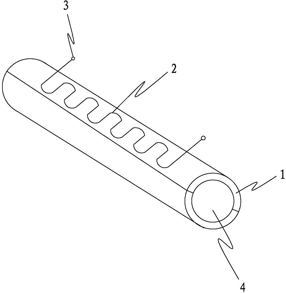
[0017] refer to figure 1 , the preferred embodiment provided by the present invention, a pinch-type oil saver, including two pinch tubes 1, the cross-section of the two pinch tubes 1 is semi-circular, and the two pinch tubes 1 are symmetrically clamped on the oil delivery pipe 4, It constitutes a casing covering the oil delivery pipe 4, and the two clamping pipes 1 are fixed by straps. Heating wires 2 are arranged on the clamping tube 1, and connecting terminals 3 for connecting to a power supply are arranged at both ends of the heating wires 2, and the heating wires 2 on different clamping tubes 1 are arranged in parallel. The surface of the pinch tube 1 is coated with a rare earth material capable of emitting infrared light waves.

[0018] The fuel economizer of the present invention can be applied to vehicles such as automobiles and ships, and can also be applied to production equipment powered by gasoline or diesel. The internal structure of the production equipment is v...


PUM


Abstract

The invention discloses a clamping-pipe-type oil economizer. The clamping-pipe-type oil economizer comprises a shell arranged outside an oil conveying pipe in a wrapped mode, wherein the shell is composed of two semi-annular clamping pipes which are symmetrically arranged, and infrared light generating material is arranged on the clamping pipes. The oil economizer can be applied to transportation tools such as automobiles and steamships and can also applied to production devices with gasoline or diesel as power, when the oil economizer is installed, the clamping pipes are directly clamped outside the oil conveying pipe, the internal structures of the automobiles, the steamships or the production devices do not need to be changed, and the oil economizer is very convenient to use. Infrared light waves generated by the infrared light generating material have constructive interference in fuel oil, the volume of the fuel oil is increased, and the oil-saving effect is achieved.

Description

technical field [0001] The invention relates to a fuel economizer, in particular to a pinch type fuel economizer. Background technique [0002] Fuel is one of the most widely used and widely used energy sources in modern times. Whether it is vehicles, ships and other means of transportation, or some production equipment, it is driven by the energy generated by fuel combustion. In order to save fuel, various fuel economizers have emerged as the times require, but the existing fuel economizers all need to be connected to the oil inlet circuit to work. It is very troublesome to change the oil circuit structure of automobiles, ships or production equipment during installation. Contents of the invention [0003] In order to solve the above-mentioned technical problems, the object of the present invention is to provide a pinch-type oil saver. [0004] The technical scheme that the present invention adopts mainly is: [0005] A pinch-type oil saver includes a shell covering the...

Claims


Application Information

Patent Timeline
IPC IPC(8): F02M27/06F02M31/125
CPCY02T10/12
Inventor 陈振圳
Owner 郑振妍
Why Eureka
Try Eureka