
An energy absorbing device using material limit characteristics and its manufacturing method

An energy absorbing device and characteristic technology, applied in elastic shock absorbers and other directions, can solve the problems of poor predictability, excessive load fluctuation and high cost, and achieve the effects of stable failure mode, good load stability and high space utilization.

Active Publication Date: 2017-07-07
CHINA NUCLEAR POWER ENG CO LTD
View PDF7 Cites 0 Cited by
  • Summary
  • Abstract
  • Description
  • Claims
  • Application Information

AI Technical Summary

Problems solved by technology

Composite cylindrical tube - the failure mode is complex and diverse, the predictability is poor, and the failure process is accompanied by debris generation; metal cylindrical tube - the load fluctuation of the plastic metal cylindrical tube is too large during the progressive crushing process, and the load of the brittle metal cylindrical tube The change is drastic, the energy absorption is not easy to predict, and there is fragmentation; foamed aluminum - the load of plastic foamed aluminum increases too rapidly in the dense compression stage, and the brittle foamed aluminum is accompanied by debris detachment during the compression process, and the load occurs locally with the fracture of the cell body Jitter; hat-shaped structure - the load stability of single-hat and double-hat structures is not good, and the hat-shaped filling structure is difficult to process and high in cost

Method used


Image

  • An energy absorbing device using material limit characteristics and its manufacturing method
  • An energy absorbing device using material limit characteristics and its manufacturing method
  • An energy absorbing device using material limit characteristics and its manufacturing method

Examples


Embodiment

[0037] A specific embodiment of the present invention is provided below, in which the selection of materials and dimensions is not limiting, and those skilled in the art can fully design this energy absorbing device according to the actual situation.

[0038] 1) Materials:

[0039] Energy-absorbing tube--304L yield strength 205MPa tensile strength 520MPa;

[0040] T-shaped head and bottom plate - 42CrMoA yield strength 780MPa tensile strength 980MPa.

[0041] 2) Structure:

[0042] The outer diameter of the energy-absorbing tube is 219mm, the wall thickness is 12mm, and the height is 356mm;

[0043] The number of preset slots for the energy-absorbing tube is 6, and the preset cracking length is 50mm;

[0044] The chamfering radius of the T-shaped head is 50mm, and the pre-pressed energy-absorbing tube is 80mm.

[0045] 3) Performance:

[0046] The effective energy-absorbing displacement of the energy-absorbing structure is 145mm;

[0047] The impact load of the energy-abso...


PUM


Abstract

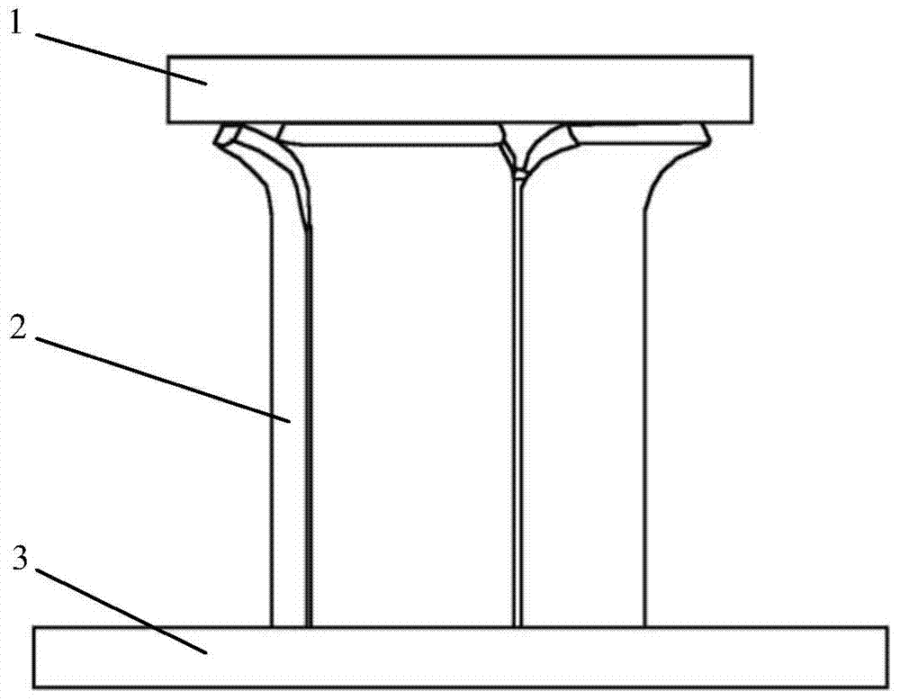
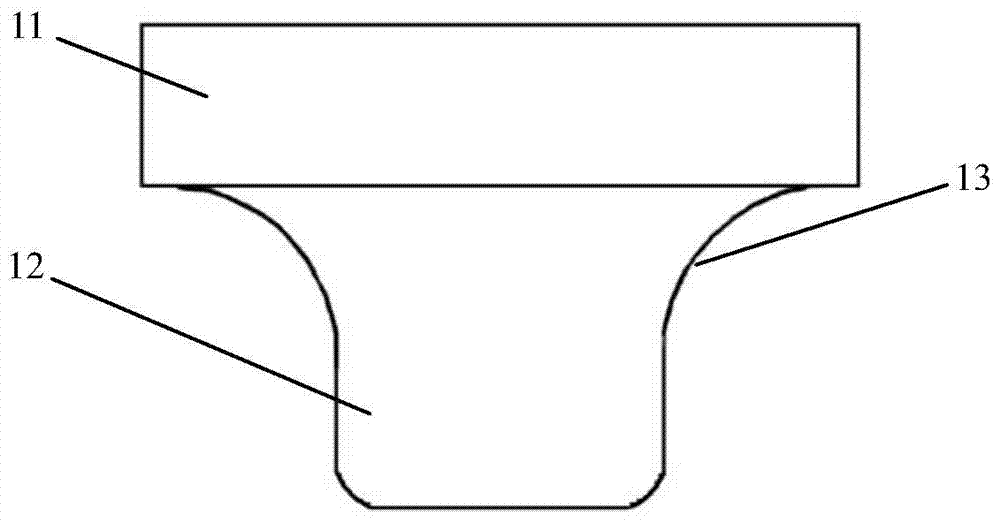
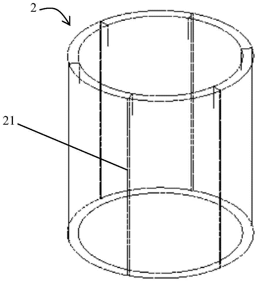
The invention relates to the field of energy absorption devices, in particular to an energy absorption device adopting the material limit characteristic, and a manufacturing method of the energy absorption device. The energy absorption device comprises a T-shaped head, an energy absorption tube and a bottom plate, wherein the bottom plate is fixed on a structure needing to be protected; one end of the energy absorption tube is connected with the bottom plate; the T-shaped head is inserted into the other end of the energy absorption tube, and structurally consists of an upper cylinder and a lower cylinder; the diameter of the lower cylinder is smaller than that of the upper cylinder; the upper cylinder is smoothly connected with the lower cylinder through a circular arc surface; one section, in contact with the T-shaped head, of the energy absorption tube is of a segmented structure; each segment part is tightly attached to the circular arc surface of the T-shaped head and is bent outwards. The energy absorption device has the advantages of being stable in destroy mode, good in load stability, good in energy absorption effect, simple in manufacturing process, flexible in adjustment, high in space utilization rate and the like.

Description

technical field [0001] The invention relates to the field of energy-absorbing devices, in particular to an energy-absorbing device utilizing material limit characteristics and a manufacturing method thereof. Background technique [0002] Common energy-absorbing structures include composite cylindrical tubes, metal cylindrical tubes, foamed aluminum and hat-shaped structures, etc., and these energy-absorbing structures have their own shortcomings. Composite cylindrical tube - the failure mode is complex and diverse, poor predictability, and the failure process is accompanied by debris generation; metal cylindrical tube - the load fluctuation of the plastic metal cylindrical tube is too large during the progressive crushing process, and the load of the brittle metal cylindrical tube The change is drastic, the energy absorption is not easy to predict, and there is fragmentation; foamed aluminum - the load of plastic foamed aluminum increases too rapidly in the dense compression...

Claims


Application Information

Patent Timeline
Patent Type & Authority Patents(China)
IPC IPC(8): F16F7/12
Inventor 盛锋刘树斌张双旺徐国飞王元珠于凤云王付军
Owner CHINA NUCLEAR POWER ENG CO LTD
Learn More