Crankshaft plane parallelism detection device

A technology of plane parallelism and detection device, which is applied in the direction of angle/taper measurement, etc., can solve the problems of no crankshaft plane parallelism detection device, troublesome operation, low efficiency, etc., and achieve reasonable structure, simple movement and adjustment, and high detection efficiency Effect

Inactive Publication Date: 2014-10-08
TIANRUN IND TECH CO LTD
View PDF0 Cites 6 Cited by
  • Summary
  • Abstract
  • Description
  • Claims
  • Application Information

AI Technical Summary

Problems solved by technology

This method is cumbersome and inefficient
So far there is no literature report on a dedicated crankshaft plane parallelism detection device

Method used


Image

  • Crankshaft plane parallelism detection device
  • Crankshaft plane parallelism detection device
  • Crankshaft plane parallelism detection device

Examples


Embodiment Construction

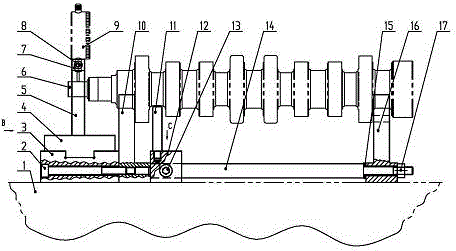
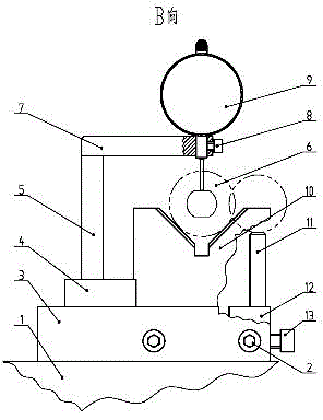
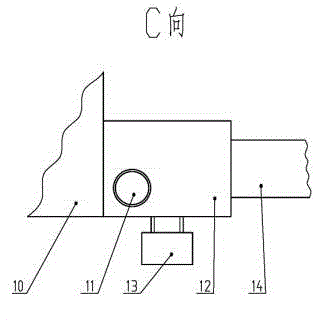
[0013] From figure 1 , figure 2 and image 3 It can be seen that a crankshaft plane parallelism detection device includes a platform 1, a slide table 3, a slide plate 4, a column 5, a crankshaft 6, a table connecting rod 7, a dial gauge 9, a V-shaped block 10, and a V-shaped block 16 , Positioning column 11, positioning support block 12 etc. The V-shaped block 10 and the V-shaped block 16 are used to support the main journals at both ends of the crankshaft 6, and the positioning support block 12 and the positioning column 11 are used to support the first connecting rod of the crankshaft. The positioning column 11 is fixed on the positioning support block 12 , and the V-shaped block 10 , the V-shaped block 16 , the positioning support block 12 and the slide table 3 are placed on the platform 1 .

[0014] Two connecting rods 14 are connected between the V-shaped block 10 and the V-shaped block 16 of the present invention, and the two ends of the connecting rods 14 are provid...


PUM


Abstract

The invention relates to a crankshaft plane parallelism detection device. The crankshaft plane parallelism detection device comprises a platform, V-shaped blocks, a positioning and supporting block, a positioning column, a sliding table, a sliding plate and a dial indicator. The V-shaped blocks, the positioning and supporting block and the sliding table are placed on the platform. Two connection pull rods are connected between the two V-shaped blocks. A circular through hole is formed in the positioning and supporting block in the direction of the connection pull rods. A smooth cylinder through which the connection pull rods are connected is movably sleeved with the positioning and supporting block, and a positioning screw is arranged in the positioning and supporting block. The sliding table is fixed to the left side of the V-shaped block at the left end through two lengthened screws. The sliding plate is movably arranged on the sliding table. A stand column is fixed to the sliding plate. The dial indicator is arranged on the stand column through a dial indicator connection rod. By means of the crankshaft plane parallelism detection device, a read number is obtained when the contact of the dial indicator makes contact with the plane at the small end of a crankshaft, and the crankshaft plane parallelism detection result can be obtained when the read number is compared with that of a standard crankshaft. The crankshaft plane parallelism detection device is reasonable in structure, easy and convenient to move and regulate, high in detection efficiency and particularly suitable for detecting the parallelism of a plane machined on a small-end cylinder of the crankshaft.

Description

technical field [0001] The invention relates to a detection device for the parallelism of parts, in particular to a detection device for the parallelism of a crankshaft plane. Background technique [0002] We know that some cylinders at the small end of the crankshaft need to be machined with symmetrical planes, and the planes have parallelism requirements. Usually, the measurement is carried out on the platform with V-shaped blocks, and the center plane is found with the first connecting rod journal and the main journal, and then used The dial indicator measures the parallelism value. This method is troublesome and inefficient. So far, there is no literature report on a dedicated crankshaft plane parallelism detection device. Contents of the invention [0003] The technical problem to be solved by the present invention is to overcome the deficiencies of the above-mentioned prior art, and provide a crankshaft plane parallelism detection device with reasonable structure, ...

Claims


Application Information

Patent Timeline
Patent Type & Authority Applications(China)
IPC IPC(8): G01B5/24
Inventor 刘洪福于海明张亚宋文友
Owner TIANRUN IND TECH CO LTD
Why Eureka
Try Eureka