Ionitriding equipment fault diagnosis system

A technology of ion nitriding and equipment failure, applied in the direction of measuring devices, instruments, measuring electricity, etc., can solve problems such as failure of ion nitriding equipment to be found in time, to avoid failure to be found in time, high accuracy and efficiency, and easy follow-up maintenance. Effect

Active Publication Date: 2014-10-08
JIANGHAN UNIVERSITY
View PDF4 Cites 2 Cited by
  • Summary
  • Abstract
  • Description
  • Claims
  • Application Information

AI Technical Summary

Problems solved by technology

[0006] In order to solve the problem that the faults of the ion nitriding equipment in the prior art cannot be found in time, and when the ion nitriding equipment fails, the fault diagnosis and maintenance are all based on the experience of the maintenance personnel, the embodiment of the present invention provides a Fault Diagnosis System of Ion Nitriding Equipment

Method used


Image

  • Ionitriding equipment fault diagnosis system
  • Ionitriding equipment fault diagnosis system
  • Ionitriding equipment fault diagnosis system

Examples


Embodiment

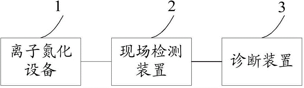
[0040] An embodiment of the present invention provides a fault diagnosis system for ion nitriding equipment, see Figure 1 ~ Figure 3 , the system consists of:

[0041] An on-site detection device 2 connected to the ion nitriding equipment 1, a diagnostic device 3 connected to the on-site detection device 2;

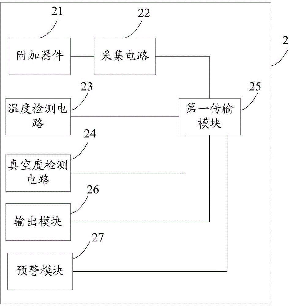
[0042] The on-site detection device 2 is used to obtain the parameters of the nodes of the ion nitriding equipment, and the nodes of the ion nitriding equipment include the power system of the ion nitriding equipment, the circuit in the action control board and the vacuum system, and the furnace body of the ion nitriding equipment And cathode and anode, the parameters of the node include the current value of the node, the voltage value of the node, the switch data of the node, the temperature of the node, the vacuum degree of the node, and the switch data includes on and off;

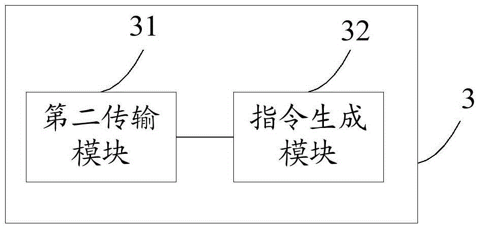
[0043] The diagnosis device 3 is used to judge whether the ion nitriding equipment fails acco...


PUM


Abstract

The invention discloses an ionitriding equipment fault diagnosis system, and belongs to the field of ionitriding. The system comprises an onsite detection device connected with ionitriding equipment and a diagnosis device connected with the onsite detection device. The onsite detection device is used for obtaining the parameter of each node of the ionitriding equipment. The nodes comprise a power system of the ionitriding equipment, a circuit in a motion control panel and vacuum system, and a furnace body, an anode and a cathode of the ionitriding equipment. The parameters of the nodes comprise node current values, node voltage values, node switching quantity data, node temperatures and node vacuum degrees. The switching quantity data comprise connection and disconnection. The diagnosis device is used for determining whether the ionitriding equipment fails according to the parameters of the nodes and outputting a diagnosis result. The fault diagnosis accuracy is high, and subsequent maintenance is facilitated.

Description

technical field [0001] The invention relates to the field of ion nitriding, in particular to a fault diagnosis system for ion nitriding equipment. Background technique [0002] Ion nitriding equipment is a device that uses the physical phenomenon of glow discharge to strengthen the surface of metal materials to form a nitride layer, so that the surface of metal materials can be hardened. [0003] Taking the ion nitriding furnace as an example, the ion nitriding furnace is composed of five parts: furnace body, power supply system, action control board, vacuum system, gas supply system, and process control system. The furnace body is composed of a furnace cover, a cylinder body, a furnace chassis and a bottom frame. Cooling water is passed through the interlayer of the furnace cover, cylinder body and furnace chassis. The furnace is equipped with stainless steel and alloy aluminum double-layer heat shields. A layer of tempered glass is used for observing the situation in the ...

Claims


Application Information

Patent Timeline
Patent Type & Authority Applications(China)
IPC IPC(8): G01R31/00
Inventor 蔡利民李鹏
Owner JIANGHAN UNIVERSITY
Why Eureka
Try Eureka