Waveguide Integrated Imaging 3D Display System Based on Diffractive Optical Elements

A diffractive optical element and three-dimensional display technology, applied in optical elements, optical waveguide light guides, optics, etc., can solve the problems of heavy weight, large volume, complex structure, etc., and achieve the effect of high transmittance and large system pupil

Active Publication Date: 2017-04-05
BEIJING INSTITUTE OF TECHNOLOGYGY
View PDF3 Cites 0 Cited by
  • Summary
  • Abstract
  • Description
  • Claims
  • Application Information

AI Technical Summary

Problems solved by technology

[0004] The technical problem to be solved by the present invention is how to provide a see-through integrated imaging three-dimensional display system with high transmittance and large system pupils, while avoiding the large volume, heavy weight and complex structure of the traditional system, which is difficult to achieve integrated Disadvantages of

Method used


Image

  • Waveguide Integrated Imaging 3D Display System Based on Diffractive Optical Elements
  • Waveguide Integrated Imaging 3D Display System Based on Diffractive Optical Elements
  • Waveguide Integrated Imaging 3D Display System Based on Diffractive Optical Elements

Examples


Embodiment 3

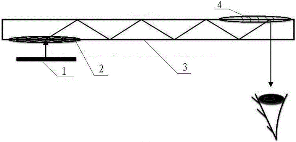
[0045] In embodiment 3, such as Figure 4 As shown, the input diffractive optical element 2 is a combination of a transmission holographic microlens array and a transmission holographic lens, located on the lower surface of the input end of the slab waveguide, and the output diffractive optical element 4 is a reflective holographic lens, located on the lower surface of the slab waveguide the top surface of the output. The combination of the transmissive holographic microlens array and the transmissive holographic lens has the functions of the holographic microlens array and the holographic lens.

Embodiment 4

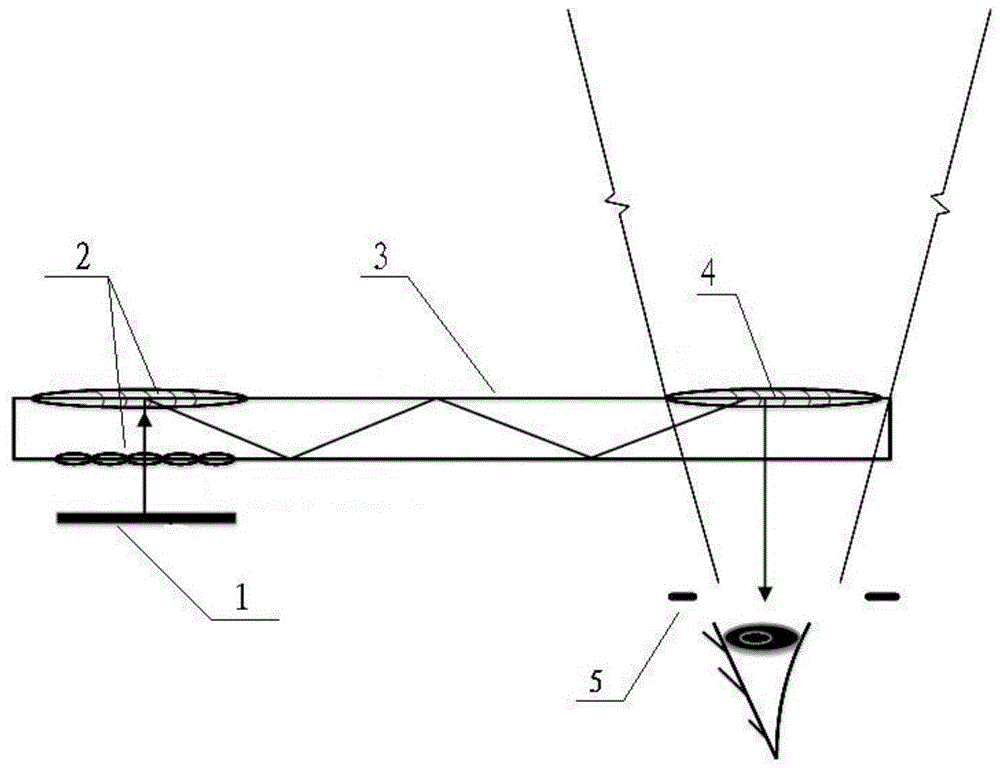
[0046] In embodiment 4, such as Figure 5 As shown, the input diffractive optical element 2 is a combination of a transmission holographic microlens array and a transmission holographic lens, located on the lower surface of the input end of the slab waveguide, and the output diffractive optical element 4 is a transmission holographic lens, located on the lower surface of the slab waveguide the lower surface of the output. The combination of the transmissive holographic microlens array and the transmissive holographic lens has the functions of the holographic microlens array and the holographic lens.

Embodiment 5

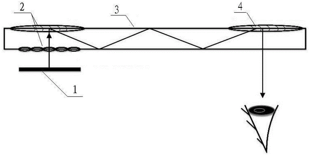
[0047] In embodiment 5, such as Figure 6 As shown, the input diffractive optical element 2 is a combination of reflective holographic microlens array and reflective holographic lens, located on the upper surface of the input end of the slab waveguide, and the output diffractive optical element 4 is a reflective holographic lens, located on the slab waveguide the top surface of the output. The combination of the reflective holographic microlens array and the reflective holographic lens has the functions of the holographic microlens array and the holographic lens.


PUM


Abstract

The invention relates to a waveguide type integrated imaging three-dimensional display system based on a diffraction optical element. A micro displayer (1) is arranged at the position of the focal length of a holographic microlens array of the surface of the input end of a waveguide (3), a two-dimensional element image passes through the holographic microlens array and is imaged to obtain an image including depth and parallax information, the obtained image is coupled into the transparent waveguide (3) through a holographic lens on the surface of the input end of the waveguide (3), is spread through total reflection and is output in a coupling mode through a holographic lens on the surface of the output end of the waveguide (3), and the image is observed by the human eyes. According to the system, the diffraction optical element is introduced in to overcome the defects that in the technical background, the size is large, the weight is large, and the structure is complex, and integrated monocular three-dimensional displaying is achieved. Meanwhile, the optical element, the waveguide (3), is introduced in, and off-axis large-system pupil sight-thorough monocular three-dimensional displaying with the high transmission rate is achieved. The system can be widely applied to integrated imaging three-dimensional display systems.

Description

technical field [0001] The invention relates to the field of integrated imaging three-dimensional display, in particular to a waveguide integrated imaging three-dimensional display system based on diffractive optical elements. Background technique [0002] The integrated imaging system is a true three-dimensional display system that uses a microlens array to record and reproduce three-dimensional information in object space, and can realize monocular stereoscopic imaging display. However, the existing integrated imaging system has the disadvantages of large volume, heavy weight, and complex structure, and it is difficult to realize integration; at the same time, the existing integrated imaging system cannot simultaneously realize see-through 3D display with high transmittance and large system pupil. Contents of the invention [0003] (1) Technical problems to be solved [0004] The technical problem to be solved by the present invention is how to provide a see-through int...

Claims


Application Information

Patent Timeline
Patent Type & Authority Patents(China)
IPC IPC(8): G02B27/22G02B27/42G02B6/12
Inventor 刘娟韩剑王涌天
Owner BEIJING INSTITUTE OF TECHNOLOGYGY
Why Eureka
Try Eureka