Touch panel having press detection function and pressure sensitive sensor for the touch panel

a technology touch panel, which is applied in the direction of force measurement, instruments, force measurement, etc., can solve the problems of poor transmission (visibility), difficult to allow the surface of pressure sensitive ink layer to have an even height, and poor visibility of the display unit of the display device. to achieve the effect of suppressing deviation, suppressing degradation of display unit visibility, and not lowering transmission (visibility)

Inactive Publication Date: 2012-01-10
NISSHA PRINTING COMPANY
View PDF21 Cites 87 Cited by
  • Summary
  • Abstract
  • Description
  • Claims
  • Application Information

AI Technical Summary

Benefits of technology

[0008]Therefore, an object of the present invention is to improve the above-mentioned issues, and thus to provide a touch panel having a press detection function that can suppress degradation of visibility of the display unit of the display device and also to improve the pressure measuring precision even when mounted on an electronic device, as well as a pressure sensitive sensor used for the touch panel.
[0042]In accordance with the touch panel having a press detection function and the pressure sensitive sensor for the touch panel of the present invention, since the pair of electrodes are disposed in the frame form along the edge portion of the first or second substrate, the transmittance of the inner portion surrounded by the frame is not lowered. Therefore, even when mounted on an electronic device, degradation of visibility of the display unit can be suppressed by disposing the display unit of the display device on the inner side of the frame. Moreover, since the pressure sensitive ink members are scattered along the edge portion of the first or second substrate, it is possible to suppress deviations of the area where the pressure sensitive ink member is made in contact with both of the pair of electrodes when an equal pressure is applied to the first substrate. Therefore, it is possible to improve the pressure measuring precision.

Problems solved by technology

Since the sensor of Japanese Unexamined Patent Publication No. 2002-48658 is designed such that electrodes and pressure sensitive ink layers are disposed on most of the portions of the surfaces of the upper and lower films, the transmittance (visibility) is poor.
For this reason, in a case where a touch panel to which the sensor of Japanese Unexamined Patent Publication No. 2002-48658 is attached is mounted as it is on an electronic device, the visibility of the display unit of the display device becomes poor.
Moreover, since each of the upper and lower films normally has a warp though little, it is difficult to allow the surface of the pressure sensitive ink layer to have an even height.
A resulting problem is that the pressure measuring precision is lowered.
In particular, as the pressure to be applied to the upper film becomes smaller, the lowering of the pressure measuring precision becomes more significant.

Method used


Image

  • Touch panel having press detection function and pressure sensitive sensor for the touch panel
  • Touch panel having press detection function and pressure sensitive sensor for the touch panel
  • Touch panel having press detection function and pressure sensitive sensor for the touch panel

Examples


first embodiment

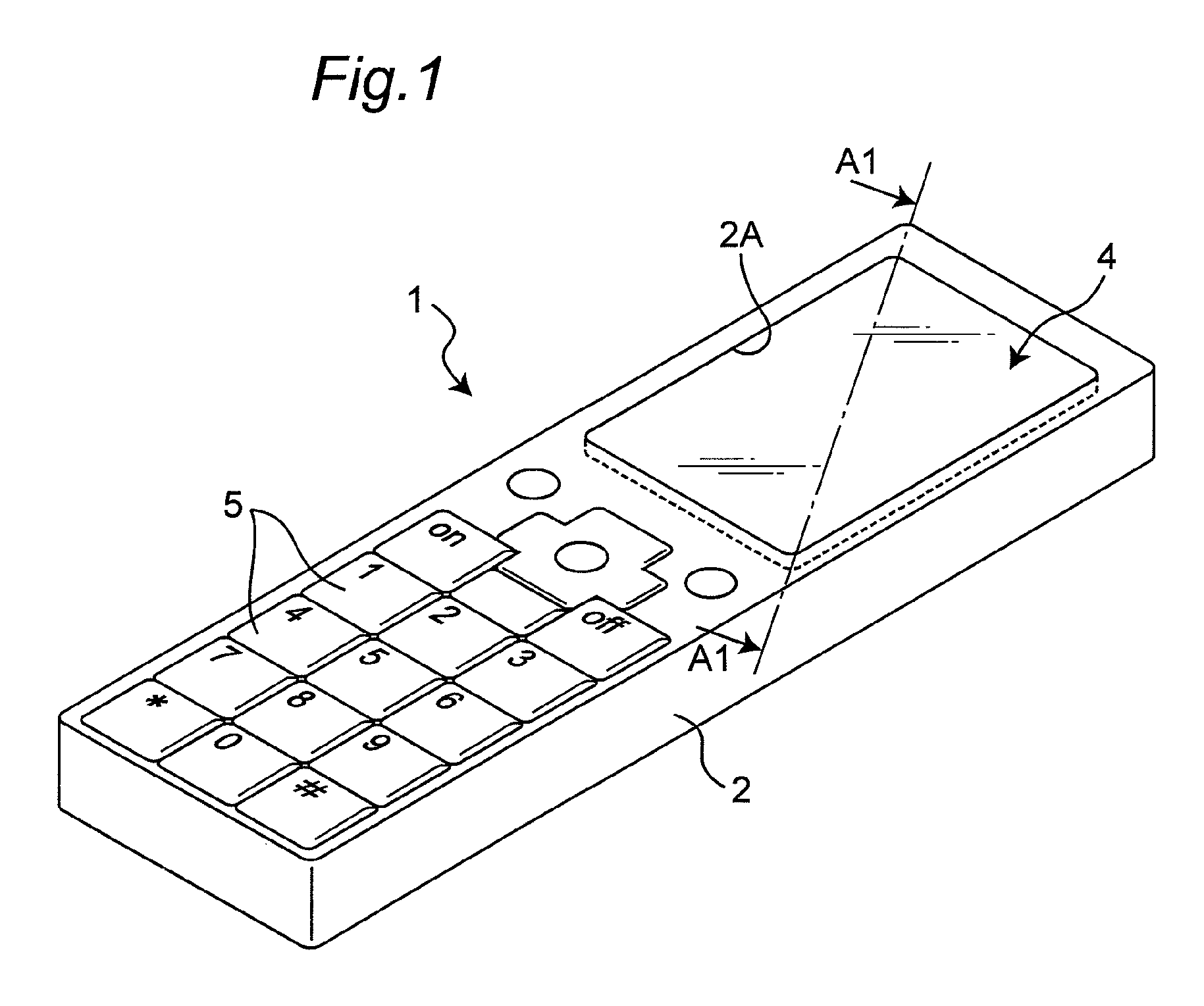
[0085]A touch panel having a press detection function in accordance with a first embodiment of the present invention has a structure in which a tough panel main body and a pressure sensitive sensor are integrally configured so that, in addition to detection of a position on the tough panel main body, a strength of a pressing force can be detected by the pressure sensitive sensor. In the following description, this touch panel having the press detection function is referred to as a touch input panel. The touch input device in accordance with the first embodiment preferably functions as a touch input device for a display of a portable electronic device, such as an electronic device, in particular, a portable telephone or a game machine. In the first embodiment, the description will be given by exemplifying a structure in which the tough input device is mounted on a portable telephone.

[0086]FIG. 1 is a perspective view exemplifying a portable telephone in which the touch input device i...

second embodiment

[0125]FIG. 16 is a plan view that shows a pressure sensitive sensor 20A included in a tough input device in accordance with a second embodiment of the present invention, and FIG. 17 is a cross-sectional view taken along line A3-A3 in FIG. 16. FIG. 18 is an exploded perspective view that shows the pressure sensitive sensor 20A shown in FIG. 16. The touch input device in accordance with the second embodiment is different from the touch input device of the first embodiment in that, in place of the upper electrode 21a, a lower electrode 22b having a rectangular frame shape is disposed on the lower film 22 in parallel with the lower electrode 22a. That is, paired electrodes in the rectangular frame shape are disposed on the lower film 22 with a predetermined gap therebetween so that the inner electrode in the rectangular frame shape corresponds to the lower electrode 22a of the first embodiment and the outer electrode in the rectangular frame shape corresponds to the upper electrode 21a ...

third embodiment

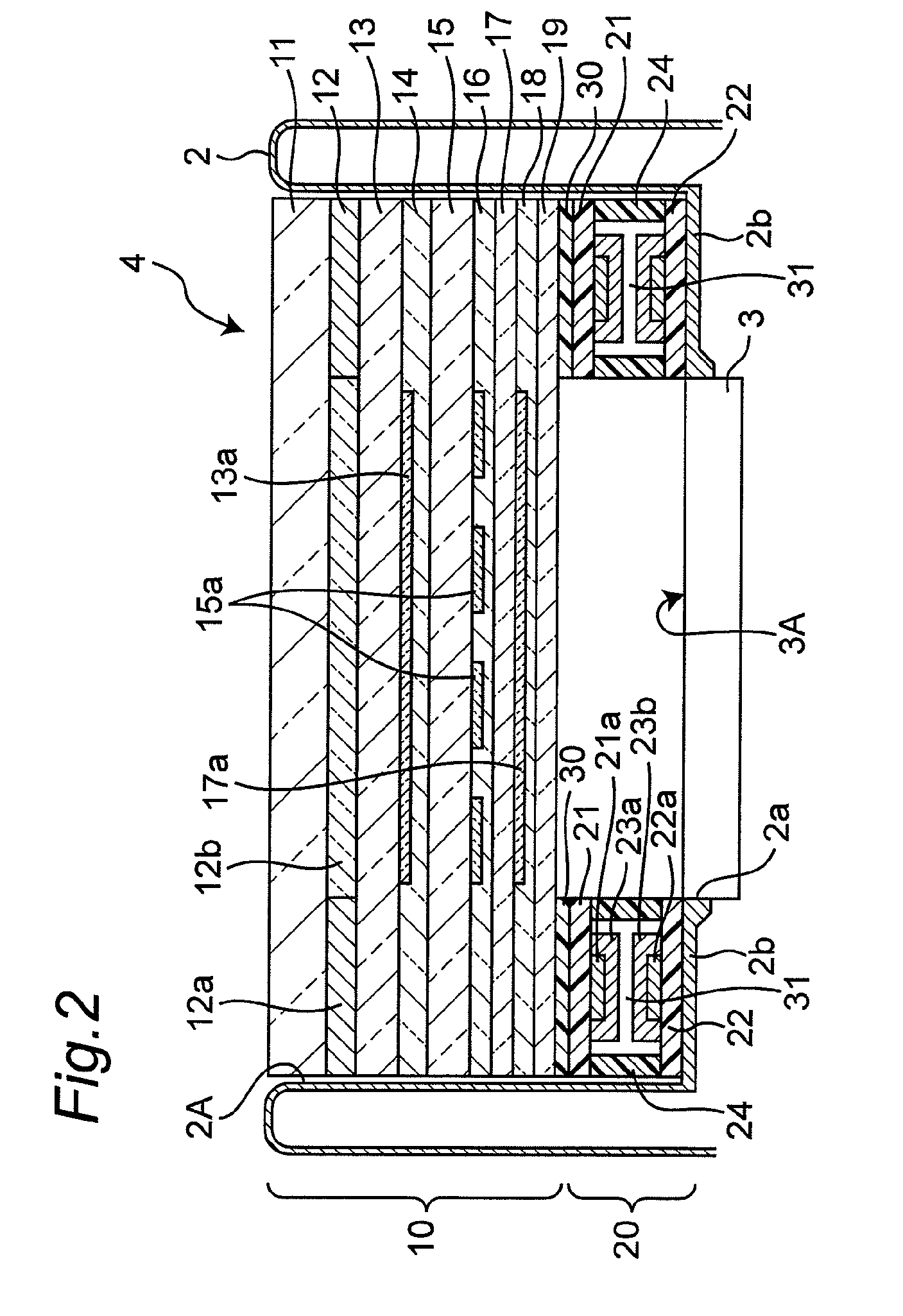
[0127]FIG. 19 is a plan view that shows a pressure sensitive sensor 20B included in a tough input device in accordance with a third embodiment of the present invention, and FIG. 20 is a cross-sectional view taken along line A1-A1 in FIG. 19. The touch input device in accordance with the third embodiment is different from the touch input device of the first embodiment in that, in place of the upper and lower films 21 and 22 in the rectangular frame shapes, upper and lower films 21A and 22A in rectangular sheet shapes are provided therein. Moreover, in the touch input device in accordance with the third embodiment, the upper and lower films 21A and 22A and the gap retaining member 24 are made of transparent materials.

[0128]In accordance with the touch input device of the third embodiment, since each of the upper and lower electrodes 21a and 22a is disposed in the rectangular frame shape so that the transmittance of the inner portion surrounded by the rectangular frame is not lowered. ...


PUM


Abstract

An object of the present invention is to provide a touch panel having a press detection function, which makes it possible to suppress degradation of visibility of a display unit of a display device even when mounted on an electronic device, and also to improve a pressure measuring precision. For this purpose, the touch panel of the present invention includes a first substrate, a second substrate disposed oppose to the first substrate, a pair of electrodes disposed on either one of opposed surfaces of the respective substrates or disposed separately on both of the surfaces, pressure sensitive ink members disposed with a gap from at least one of the pair of electrodes, each of the pressure sensitive ink members having an electrical characteristic varied by a pressing force applied thereto, and a gap retaining member for bonding the first and second substrates to each other and for retaining a gap between each of the pressure sensitive inks and at least one of the pair of electrodes, wherein the pair of electrodes are disposed in a frame shape along an edge portion of the first or second substrate, and the pressure sensitive ink members are scattered along the edge portion of the first or second substrate so that, when the first or second substrate is deformed upon an application of an external force, at least one of them is made in contact with both of the pair of electrodes so as to make the two electrodes conductive to each other.

Description

BACKGROUND OF THE INVENTION[0001]I. Technical Field[0002]The present invention relates to a touch panel having a press detection function which, out of an external force applied to a surface, measures a component in a direction perpendicular to the surface, and a pressure sensitive sensor for the touch panel.[0003]II. Description of the Related Art[0004]Conventionally, a pressure sensitive sensor has been known as a sensor having a press detection function for measuring a pressure of an external force (referred to also as a pressing force) that is applied to a certain surface. As this pressure sensitive sensor, for example, a sensor having a structure described in Japanese Unexamined Patent Publication No. 2002-48658 has been known. The sensor of Patent Document 1 is designed such that plastic films, each formed by stacking an electrode and a pressure sensitive ink layer thereon in this order, are combined with each other so as to make the pressure sensitive ink members face each ot...

Claims


Application Information

Patent Timeline
Patent Type & Authority Patents(United States)
IPC IPC(8): G06F3/041
CPCG01L1/205G06F3/044G06F3/045G02F1/13338G06F2203/04105G06F3/0445G06F3/0446G06F3/0447G06F2203/04103
Inventor SUZUKI, TAKAHIROKAI, YOSHIHIROENDO, YUKOTAKAI, YUICHIROSHIMIZU, JUNYAMAOKA, YOSHITAKAOKUMURA, SHUZOHIRAI, SEIKOIMAI, YOHKO
Owner NISSHA PRINTING COMPANY
Why Eureka
Try Eureka