Intelligent charger with output voltage changing function

An output voltage and charger technology, applied in the field of communication, can solve the problems of long charging time and high power consumption of intelligent terminals, and achieve the effect of improving output power, satisfying fast charging and ensuring safety.

Inactive Publication Date: 2014-10-08
SHENZHEN SIECOM COMM TECH DEV CO LTD
4 Cites 61 Cited by

AI-Extracted Technical Summary

Problems solved by technology

[0002] Due to the larger screen and more applications of the smart terminal, the power consumption of the smart terminal is increasing, and the battery capacity of the correspondin...

Method used

[0030] Please refer to FIG. 3, which is a structural schematic diagram of the power supply unit of the charger with intelligent variable output voltage shown in FIG. 1. The power supply unit 20 includes a switch K, through which the output voltage value is switched, such as +5V, V1, V2 and so on. In this embodiment, the switch K is a single-pole multi-throw switch. When working, the power supply unit 20 switches the single-pole multi-throw switch K under the control of the processing unit 10, so as to realize +5V, V1, V2 and other different voltage outputs. The processing unit 20 performs handshake communication with the smart terminal 2 connected to the charger, and controls the single-pole multi-throw switch according to the requirements of the smart terminal 2, so that the voltage output by the charger meets the requirements ...

Abstract

The invention discloses an intelligent charger with an output voltage changing function. The intelligent charger comprises a processing unit, a power unit and an interface unit. The processing unit is connected with the power unit and the interface unit. The power unit is connected with the interface unit. The interface unit is connected with an external intelligent terminal. The processing unit conducts handshake and communication with the intelligent terminal through the interface unit and controls the output voltage of the power unit according to handshake and communication results so that the output voltage of the power unit can reach the requirements of the intelligent terminal. The intelligent charger can intelligently switch the output voltages according to the requirements of the intelligent terminal to charge the intelligent terminal and accelerate charging. The invention further discloses a charging method applied to the intelligent charger.

Application Domain

Technology Topic

Image

  • Intelligent charger with output voltage changing function
  • Intelligent charger with output voltage changing function
  • Intelligent charger with output voltage changing function

Examples

  • Experimental program(1)

Example Embodiment

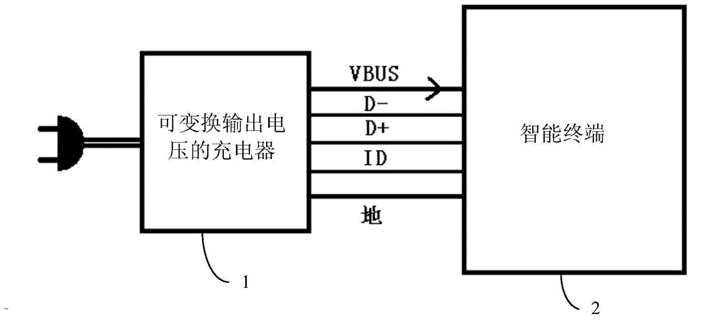
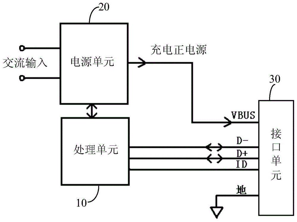
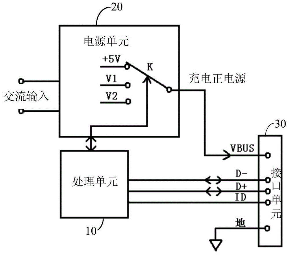
[0019] In order to shorten the charging time, fast charging must be carried out. To realize fast charging, the charging power must be increased. To increase the charging power, a high-power charger is required. The traditional high-power charger increases the output under the premise of the same output voltage. Current, increasing the output current will be limited by the maximum current allowed by the charging interface, charging connection and other devices. Therefore, the method of increasing the output current to increase the output power of the charger is greatly restricted. This patent proposes the use of The method of increasing the output voltage can increase the output power of the charger. At the same time, the charger can communicate with the smart terminal by handshaking, and adjust the output voltage according to the instructions issued by the smart terminal, so as to meet the needs of fast charging of the smart terminal to the greatest extent. Therefore, the present invention provides a charger and a charging method capable of shortening the charging time with an intelligently convertible output voltage.
[0020] The invention is to increase the output power of the charger by increasing the output voltage of the charger by ensuring that the power supply current is within the allowable range of the universal interface device, the charging power connection and the like.
[0021] The output power formula of the charger is: P=U×I
[0022] Where P is the output power of the charger, U is the output voltage, and I is the output current.
[0023] It can be seen from the above formula that under the condition that the charger output current I is constant, its output power P increases proportionally with the increase of the output voltage U. Therefore, the present invention increases the output voltage while keeping the output current stable, thereby accelerating charging.
[0024] The technical solutions in the embodiments of the present invention will be clearly and completely described below in conjunction with the accompanying drawings of the specification of the present invention. Obviously, the described embodiments are part of the embodiments of the present invention, not all of the embodiments. Based on the embodiments of the present invention, all other embodiments obtained by those of ordinary skill in the art without creative work shall fall within the protection scope of the present invention. For the convenience of description, the "charger" or "smart charger" mentioned below all refer to the intelligently convertible output voltage charger of the present invention.
[0025] See figure 1 , Is a schematic diagram of the connection between an embodiment of the intelligently convertible output voltage charger of the present invention and the intelligent terminal. One end of the intelligently convertible output voltage charger 1 is connected to external alternating current, and the other end is connected to the smart terminal 2 to be charged. As shown in the figure, VBUS is the positive power supply for charging, which is the positive power supply for the smart charger to charge or supply power to the smart terminal; the positive power supply VBUS and ground form the power supply loop for the charger to charge and supply power to the smart terminal; D+/ D- is used to transmit data during communication between the charger and the smart terminal; ID is used for detection.
[0026] See also figure 2 , figure 1 The illustrated charger 1 with a convertible output voltage includes a processing unit 10, a power supply unit 20, and an interface unit 30. The processing unit 10 is a central processing unit (CPU) or a microprocessor (MCU), the power supply unit 20 is a power supply unit with a controllable output voltage, and the interface unit 30 is a USB interface. The processing unit 10 is connected to the power supply unit 20 and the interface unit 30. The power supply unit 20 is connected to the interface unit 30. The interface unit 30 is connected to an external intelligent terminal. The processing unit 10 performs handshake and communication with the smart terminal through the USB interface of the interface unit 30, and controls the output voltage of the power supply unit 20 according to the result of the handshake and communication, so that the output voltage of the power supply unit 20 reaches the value of the smart terminal. Requirements, so as to achieve the purpose of fast charging with high voltage.
[0027] The output voltage of the power supply unit 20 is controlled by the processing unit 10, and the processing unit 10 adjusts the output voltage of the power supply unit 10 according to the requirements of the smart terminal. When the processing unit 10 does not issue an instruction to the power supply unit 20, the default output voltage of the power supply unit 20 is +5V, which is compatible with common chargers on the market. When the processing unit 10 issues an instruction to the power supply unit 20, the power supply unit 20 outputs a corresponding voltage according to the instruction of the processing unit 10, thereby accelerating the charging of the smart terminal by intelligently transforming the output voltage.
[0028] The interface unit 30 is a communication interface between the intelligently convertible output voltage charger and the intelligent terminal. In the foregoing embodiment of the present invention, the interface unit 30 adopts a USB interface mode, an interface for powering and charging the smart terminal through VBUS and ground. The VBUS of the USB interface is different from the usual USB interface. The default voltage of the VBUS of the USB interface is +5V, and the voltage will increase during fast charging to meet the requirements of fast charging.
[0029] At the same time, the AC input interface adopted by the present invention can meet the AC voltage and frequency of the commercial power of all countries in the world, and is a wide-voltage AC input interface.
[0030] See image 3 ,Yes figure 1 The structure diagram of the power supply unit of the intelligently convertible output voltage charger. The power supply unit 20 includes a switch K, through which the output voltage value, such as +5V, V1, V2, etc., is switched. In this embodiment, the switch K is a single-pole multi-throw switch. During operation, the power supply unit 20 switches the single-pole multi-throw switch K under the control of the processing unit 10, so as to realize different voltage outputs such as +5V, V1, V2. The processing unit 20 performs handshake communication with the smart terminal 2 connected to the charger, and controls the single-pole multi-throw switch according to the requirements of the smart terminal 2 so that the voltage output by the charger meets the requirements of the smart terminal 2. Finally, realize the requirement of high-power fast charging with high voltage. In the above embodiment, V2>V1>+5V, and the charger outputs different levels of voltage V1 or V2 according to the requirements of the smart terminal 2, so as to realize fast charging.
[0031] See Figure 4 ,Yes figure 1 A schematic diagram of another embodiment of the smart charger capable of converting output voltage.
[0032] In this embodiment, the power supply unit 20 includes a DC/DC conversion circuit, a pull-up resistor R and a pull-down resistor VR. The output voltage V+ of the power supply unit 20 is connected to the VBUS end of the interface unit 30, and is grounded through the pull-up resistor R and the pull-down resistor VR in sequence. The node A between the pull-up resistor R and the pull-down resistor VR is electrically connected to the DC/DC conversion circuit as a feedback end. The pull-down resistor VR is an adjustable resistor, and the processing unit 10 is connected to the pull-down resistor VR and can control the resistance value of the pull-down resistor VR.
[0033] The power supply unit 20 adjusts the output voltage of the power supply by adjusting the resistance value in the voltage conversion feedback circuit and can meet the requirements for high-power fast charging of the terminal by increasing the output voltage of the charger. Further, the reference voltage of the feedback at point A is:
[0034] VA=[V+/(R+VR)]*VR
[0035] Among them, VA represents the voltage value at A, which is also the reference voltage value for voltage feedback. The DC/DC conversion circuit samples the reference voltage fed back at the feedback terminal A,
[0036] When the resistance value of the pull-down resistor VR is sampled by the conversion voltage, the feedback reference voltage VA can be obtained according to the above formula also changes, the feedback reference voltage changes, and the DC output voltage V+ also changes, so that the processing unit 10 controls the power supply The output voltage value of the unit 20 realizes continuous conversion output of the output voltage.
[0037] In the above-mentioned embodiments, the charger with an intelligent and convertible output voltage of the present invention can achieve the purpose of adjusting the output voltage, and finally realizes the method of increasing the output voltage of the charger to increase the output power, so as to meet the requirements of high-power fast charging of the terminal. Demand.
[0038] See Figure 5 , Is a schematic block diagram of another embodiment of a charger with an intelligently convertible output voltage of the present invention. The intelligently convertible output voltage charger includes a processing unit 10, a power supply unit 20, an interface unit 30, an analog-to-digital conversion unit 40, a voltage difference amplifier 50 and a current sampling resistor R. The current sampling resistor R is arranged between the power supply unit 20 and the interface unit 30 for sampling the output current. The analog-to-digital conversion unit 40 (also called an ADC conversion unit) converts the sampled output current into a digital signal and sends it to the processing unit 10 for processing. The processing unit 10 includes a central processing unit, and the central processing unit determines and controls the current output by the power supply unit 10 according to the received digital signal. During operation, the processing unit 10 can control the power supply unit 20 to output or turn off the power output according to the received digital signal corresponding to the output current, so as to ensure the safety of the entire charging system (charger and smart terminal).
[0039] See Image 6 , Is a schematic flow chart of the charging method for intelligently convertible output voltage of the present invention. The charging method for intelligently convertible output voltage of the present invention includes:
[0040] Step S01, connect the smart charger and the smart terminal;
[0041] Step S02, the initial output voltage of the smart charger is +5V, and the smart terminal detects the smart charger;
[0042] Step S03, the smart terminal sends instructions to the charger via USB through its own configuration, so that the charger outputs a suitable fast charging voltage;
[0043] Step S04, whether the charger receives the instruction and responds, if "yes", skip to step S05, if "no", skip to step S07;
[0044] Step S05, the smart terminal receives the response from the charger and notifies the charger when it is ready;
[0045] Step S06, the charger outputs the charging voltage according to the requirements of the smart terminal and starts fast charging;
[0046] In step S07, the smart terminal does not receive a response from the charger, and continues to charge according to the normal +5V.
[0047] Compared with the prior art, the present invention has the following beneficial effects:
[0048] 1. Use the method of increasing the output voltage to increase the output power of the charger to meet the terminal's demand for high-power fast charging.
[0049] 2. The charger has a handshake communication function, which can shake hands and communicate with the smart terminal.
[0050] 3. The patented charger performs handshake communication with the smart terminal through the USB charging interface, and can output different charging voltages according to the needs of the smart terminal.
[0051] 4. The variable output voltage of the charger is mainly realized by the following two methods: one is to realize the output of multiple voltages of the smart charger through the switching of single-pole multi-throw switches; the other is to change the charger voltage conversion parameters to achieve The output of the smart charger with continuous voltage changes.
[0052] 5. The patented charger protects itself and the load terminal by detecting the size of the output current to ensure the safety of the working system.
[0053] The invention is that the charger with the handshake communication function increases the output power by increasing the output voltage, thereby meeting the requirements of fast charging and high-power power supply for smart terminals.
[0054] The above are only the embodiments of the present invention, and do not limit the scope of the present invention. Any equivalent structure or equivalent process transformation made by using the content of the description and drawings of the present invention, or directly or indirectly applied to other related technologies In the same way, all fields are included in the scope of patent protection of the present invention.

PUM

no PUM

Description & Claims & Application Information

We can also present the details of the Description, Claims and Application information to help users get a comprehensive understanding of the technical details of the patent, such as background art, summary of invention, brief description of drawings, description of embodiments, and other original content. On the other hand, users can also determine the specific scope of protection of the technology through the list of claims; as well as understand the changes in the life cycle of the technology with the presentation of the patent timeline. Login to view more.

Similar technology patents

Safety protection method of network feedback host computer

InactiveCN101567888AEnsure safetyUnable to connectData switching networksNetwork behaviorSoftware
Owner:郭世泽 +1

Classification and recommendation of technical efficacy words

  • Ensure safety
  • Increase output power

Transaction verification method and system based on block chain

ActiveCN106548330APrevent balance leakageEnsure safetyPayment protocolsPayment circuitsVerification systemComposite number
Owner:ONE CONNECT SMART TECH CO LTD SHENZHEN

C/X dual-band microstrip antenna

Owner:UNIV OF ELECTRONIC SCI & TECH OF CHINA
Why Eureka
Try Eureka