
A urea hydrolysis reactor outlet demisting device

A technology of urea hydrolysis and demisting device, which is applied in the field of flue gas denitrification, can solve the problems that the demisting effect cannot be improved, the demisting effect is not ideal, and it is difficult to repair and replace, so as to improve the overall demisting effect and achieve comprehensive demisting Effect, convenient repair and maintenance effect

Inactive Publication Date: 2016-06-15
CHINA HUANENG GRP CO LTD +1
View PDF2 Cites 0 Cited by
  • Summary
  • Abstract
  • Description
  • Claims
  • Application Information

AI Technical Summary

Problems solved by technology

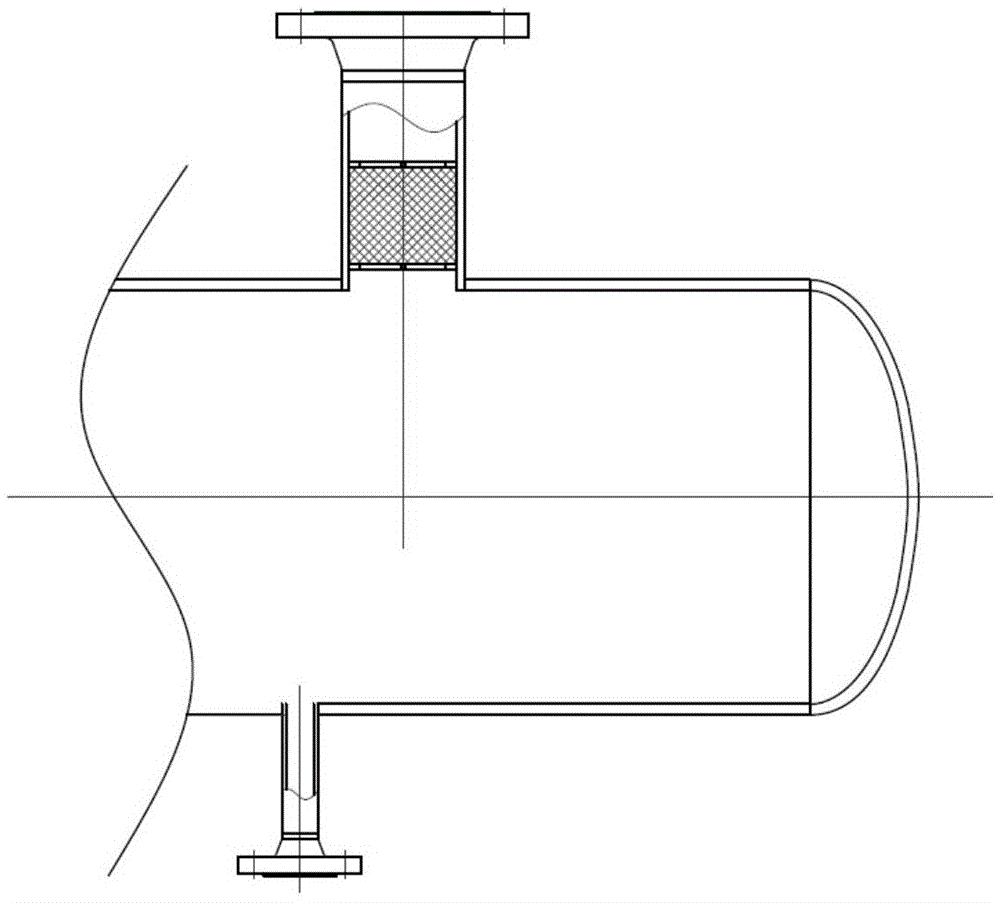
[0003] At present, the commonly used technology in the industry is to install a wire mesh demister at the outlet of the hydrolysis reactor product, such as figure 1 As shown, on the one hand, due to the large content of small droplets in the gas phase, the defogging effect is not ideal due to the limitation of the defogging ability of the wire mesh eliminator itself, and the defogging effect cannot be improved.
On the other hand, the current wire mesh demister adopts a built-in fixed structure, which is not easy to repair and replace after clogging

Method used


Image

  • A urea hydrolysis reactor outlet demisting device
  • A urea hydrolysis reactor outlet demisting device
  • A urea hydrolysis reactor outlet demisting device

Examples


Embodiment Construction

[0024] The present invention will be further described in detail below in conjunction with specific embodiments, which are explanations of the present invention rather than limitations.

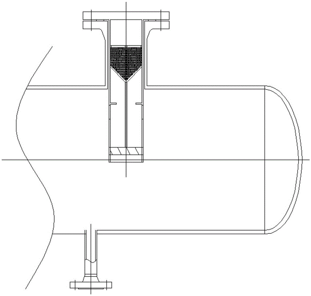
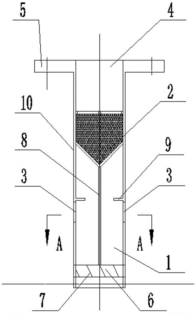
[0025] A kind of urea hydrolysis reactor outlet demister device of the present invention, as image 3 As shown, it includes a cylinder body 10, and a cyclone defogging section 1 and a wire mesh demisting section 2 which are arranged in series in the cylinder body 10 and separated by an annular partition 9; the lower end of the cylinder body 10 extends into the outlet of the urea hydrolysis reactor The upper end forms a gas phase outlet 4 and is fixed with the outlet of the urea hydrolysis reactor; the gas outlet of the wire mesh demisting section 2 is connected to the gas phase outlet 4, and the air inlet is connected to the exhaust end of the cyclone demisting section 1; the cyclone demisting The air inlet 3 of the section 1 is arranged on the side wall of the cylinder 10, and the liquid out...


PUM


Abstract

A urea hydrolysis reactor outlet defogging device of the present invention comprises a cylinder body, and a cyclone defogging section and a wire mesh demisting section arranged in series in the cylinder body and separated by an annular partition; the lower end of the cylinder body extends into the urea hydrolysis reactor The outlet is set, the upper end forms a gas phase outlet and is fixed with the outlet of the urea hydrolysis reactor; the outlet end of the wire mesh demisting section is connected to the gas phase outlet, and the inlet end is connected to the exhaust end of the cyclone demisting section; the air inlet of the cyclone demisting section is set On the side wall of the cylinder body, the liquid outlet at the lower end of the cyclone defogging section extends below the liquid level in the urea hydrolysis reactor. Demisting is carried out by using two-stage series devices. The first stage is cyclone demisting to separate large droplets, and the second stage is wire mesh demisting to separate small droplets; the airflow through the outlet of the cyclone demisting section enters the wire in the form of rotating flow. The mesh defogging section increases the length of the trajectory of the airflow in the wire mesh defogging section, improves the defogging effect of the wire mesh defogging section, obtains a better comprehensive defogging effect, and has a stronger defogging ability.

Description

technical field [0001] The invention belongs to the technical field of flue gas denitrification, and relates to a demisting device at the outlet of a urea hydrolysis reactor. Background technique [0002] The preparation of ammonia by urea hydrolysis is a reducing agent preparation process in the SCR denitrification process of flue gas in thermal power plants. The principle is that the urea solution is hydrolyzed to generate ammonia and carbon dioxide under certain temperature and pressure in the hydrolysis reactor. The generated ammonia, carbon dioxide and part of the water vapor leave the hydrolysis reactor and are sent to the boiler flue for denitrification reaction. The internal space of the hydrolysis reactor is divided into the lower liquid phase space and the upper gas phase space. Due to the violent boiling of the liquid phase space, the vapor phase space is not only filled with reaction product ammonia, carbon dioxide and partially evaporated water vapor, but also ...

Claims


Application Information

Patent Timeline
Patent Type & Authority Patents(China)
IPC IPC(8): B01J4/00B01D50/00C01C1/08
Inventor 张波张向宇向小凤徐宏杰
Owner CHINA HUANENG GRP CO LTD
Learn More