Bottom-suspension equipment mounting structure and chassis of railway vehicle

A technology for rail vehicles and installation structures, applied in the direction of chassis, transportation and packaging, railway car body parts, etc., can solve the problems of reduced passenger comfort, increased vibration, vibration and impact, etc., to improve comfort and improve installation reliability. The effect of resistance and deformation prevention

Active Publication Date: 2014-10-15
ZHUZHOU ELECTRIC LOCOMOTIVE CO
View PDF6 Cites 15 Cited by
  • Summary
  • Abstract
  • Description
  • Claims
  • Application Information

AI Technical Summary

Problems solved by technology

[0002] The under-vehicle equipment is generally installed on the chassis through the front and rear parallel suspension seats. When installing the equipment, the equipment needs to be installed from left to right or from right to left. The stable installation of the equipment cannot be guaranteed, and there is no influence on the under-vehicle equipment and the underframe. For any protection measures, when the rail vehicle is running at high speed, due to the track irregularity input and the strong interaction force between the wheel and the rail, the car body will produce severe coupling vibrations of various modes, and the equipment installed under the car body that is closely connected with the car body will simultaneously It is also subject to strong vibration and impact, and what is more serious: some hanging equipment (such as main transformers, traction fans, air compressors, etc.)
The aggravation of vibration will reduce the comfort of passengers, and even cause the fatigue fracture of the car body, equipment under the car and connecting parts

Method used


Image

  • Bottom-suspension equipment mounting structure and chassis of railway vehicle
  • Bottom-suspension equipment mounting structure and chassis of railway vehicle
  • Bottom-suspension equipment mounting structure and chassis of railway vehicle

Examples


Embodiment Construction

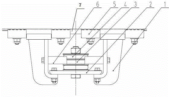
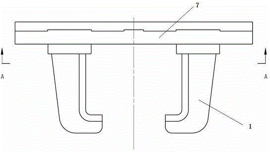
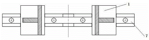
[0019] Such as figure 1 Shown, a kind of installation structure of the equipment under the rail vehicle has a suspension seat, and the suspension seat includes two suspension plates 1 installed relatively vertically, and a slide block 7 installed on the top of the suspension plate 1, as shown in FIG. figure 2 As shown, each suspension plate 1 includes a vertical plate and a horizontal plate bent toward the other suspension plate at the bottom of the vertical plate, and the support plate 2 is installed on the top surface of the horizontal plate of the two suspension seats, and the equipment 3 is installed on the support plate 2 top surface; the installation structure also includes a device vibration damping mechanism and a stopper 6 that limits the horizontal movement of the device. Two stoppers 6 are installed on each suspension plate 1, and four stoppers 6 are installed symmetrically. The vibration-damping mechanism includes vibration-damping pads 4 respectively arrange...


PUM


Abstract

The invention relates to a bottom-suspension equipment mounting structure and a chassis of a railway vehicle. The bottom-suspension equipment mounting structure comprises a suspension base comprising two suspension plates, each suspension plate comprises a vertical plate and a horizontal plate at the bottom of the vertical plate, and each horizontal plate is bent towards the other suspension plate. A supporting plate is mounted on the top surfaces of the horizontal plates of the suspension base, and equipment is mounted on the top surface of the supporting plate. The bottom-suspension equipment mounting structure comprises an equipment damping mechanism and stoppers limiting horizontal moving of the equipment. The chassis of the railway vehicle comprises a chassis beam, the lower surface of the chassis beam is provided with a C-shaped groove concave upwardly, and a slider of the bottom-suspension equipment mounting structure is mounted into the C-shaped groove. The radio of excitation frequency to system inherent frequency is within the optimal range via rubber rigidity adjustment, the problem of resonance between the equipment and the vehicle is effectively avoided, impact load during high-speed running of the vehicle and the equipment is quickly attenuated, and the stoppers of the equipment protect the equipment from large displacement.

Description

technical field [0001] The invention relates to a rail vehicle underframe, in particular to a rail vehicle undercarriage equipment installation structure and a rail vehicle underframe. Background technique [0002] The equipment under the vehicle is generally installed on the chassis through the suspension seats parallel to each other. When installing the equipment, the equipment needs to be installed from left to right or from right to left. The stable installation of the equipment cannot be guaranteed, and there is no influence on the equipment under the vehicle and the chassis. For any protection measures, when the rail vehicle is running at high speed, due to the track irregularity input and the strong interaction force between the wheel and the rail, the car body will produce severe coupling vibrations of various modes, and the equipment installed under the car body that is closely connected with the car body will simultaneously It is also subject to strong vibration an...

Claims


Application Information

Patent Timeline
Patent Type & Authority Applications(China)
IPC IPC(8): B61F1/08
Inventor 夏丹锋谢红兵吕志龙林文君周安德
Owner ZHUZHOU ELECTRIC LOCOMOTIVE CO
Why Eureka
Try Eureka