Terminal block for rotary electric machine

a terminal block and rotary electric machine technology, applied in the direction of electrical equipment, dynamo-electric machines, supports/enclosements/casings, etc., can solve the problems of inferior strength to the case, interference with another appliance, and difficulty in secure a space for mounting the connectors of power supply lines and signal lines, so as to prevent resonance, reduce vibration and sound propagation from the terminal block, and increase the number of components.

Active Publication Date: 2011-08-04
TOYOTA JIDOSHA KK +1
View PDF12 Cites 20 Cited by
  • Summary
  • Abstract
  • Description
  • Claims
  • Application Information

AI Technical Summary

Benefits of technology

[0014]The invention provides a rotary electric machine terminal block that prevents the resonance of a plate provided in the terminal block without increasing the number of component parts.
[0015]A first aspect of the invention relates to a rotary electric machine terminal block that fits into an opening of a case in which a rotary electric machine is provided, and that is fixed to the case by a presser plate. The rotary electric machine terminal block has: an electric power line connector that relays electric power to the rotary electric machine; a signal line connector that relays a sensor signal for -detecting a rotation angle of the rotary electric machine; a mount that is formed by disposing the electric power line connector and the signal line connector on the presser plate and performing insert molding so that an anti-vibration plate is formed by a resin on an upper surface of the presser plate; and a projected portion of the presser plate that is projected radially outward from the mount and that has a fixation hole for fixing the presser plate to the case, and the presser plate is made of a metal. Due to this construction, the resonance of the presser plate (metal-made plate) of the rotary electric machine terminal block is reduced by the anti-vibration plate, so that the vibration and sound propagated from the terminal block can be reduced.
[0016]Besides, a second aspect of the invention relates to a rotary electric machine terminal block that fits into an opening of case in which a rotary electric machine is provided, and that is fixed to the case by a presser plate. This rotary electric machine terminal block has: an electric power line connector that relays electric power to the rotary electric machine; a signal line connector that relays a sensor signal for detecting a rotation angle of the rotary electric machine; a mount that is formed by disposing the electric power line connector and the signal line connector on the presser plate and performing insert molding so that a lower surface of the presser plate is covered with a resin; a projected portion of the presser plate that is projected radially outward from the mount and that has a fixation hole for fixing the presser plate to the case; and a first seal member that causes the mount to be tightly attached to the case, and the presser plate is made of a metal, and the presser plate is provided with a corrugated-shape protrusion for changing a resonance frequency of the terminal block. Because of this construction, it is possible to reduce the void that is formed within the resin when the amount of resin used is reduced, and also restrain the formation of a gap between the resin and the presser plate.
[0017]The rotary electric machine terminal blocks in accordance with the invention each achieve the effect of enabling the prevention of the resonance of the plate provided in the terminal block without increasing the number of component parts. Besides, the production of the rotary electric machine terminal block, the use of the insert molding process makes it possible to mold the anti-vibration portion integrally with the upper surface of the plate, so that the production cost can be reduced.

Problems solved by technology

In this case, it is necessary that connectors for signals from rotation angle sensors needed for the control of the rotary electric machine and signals for the measurement of the coil temperature of the stator be provided separately from the first and second connectors, and it is difficult to secure a space in which to mount the connectors of the power supply lines and the signal lines.
However, the rotary electric machine terminal block 150 described in Japanese Patent Application Publication No. 2008-301544 (JP-A-2008-301544) is a die-cast component part made of a resin and aluminum, and is therefore inferior in strength to the case.
However, in such a case, the size of the composite connector 110 becomes large so that the composite connector 110 may interfere with another appliance and may not be able to be mounted.
Besides, if the plate 114 and the composite connector 110 are provided as separate members, the mounting operation becomes complicated.
Therefore, it is necessary to integrate the plate 114 and the composite connector 110 through the use of screws or the like, which makes it difficult to reduce the number of component parts.

Method used


Image

  • Terminal block for rotary electric machine
  • Terminal block for rotary electric machine
  • Terminal block for rotary electric machine

Examples


first embodiment

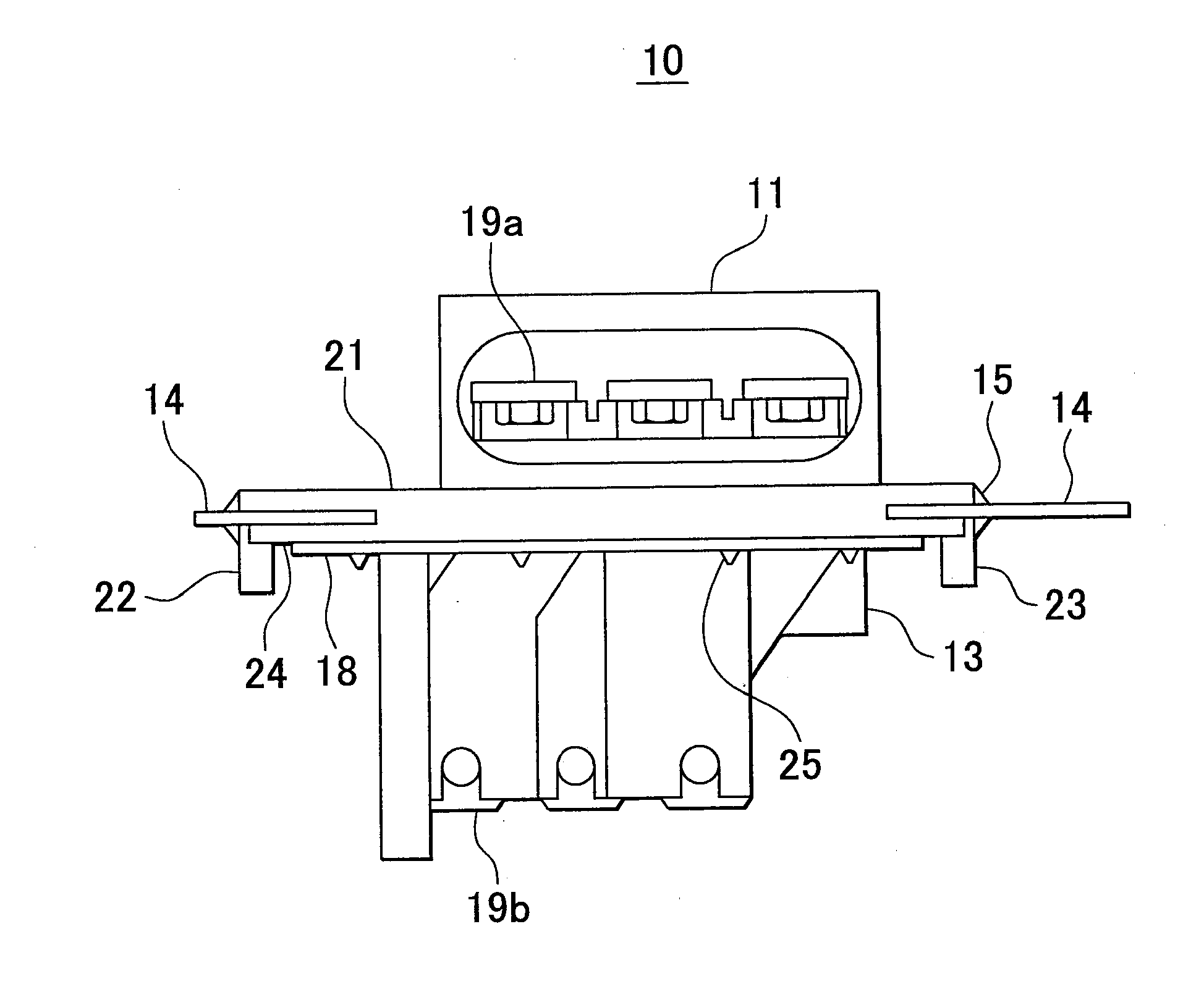
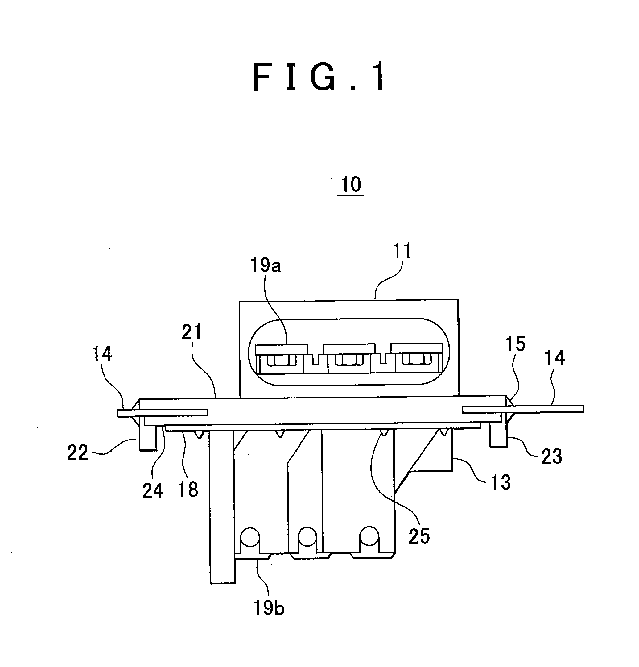
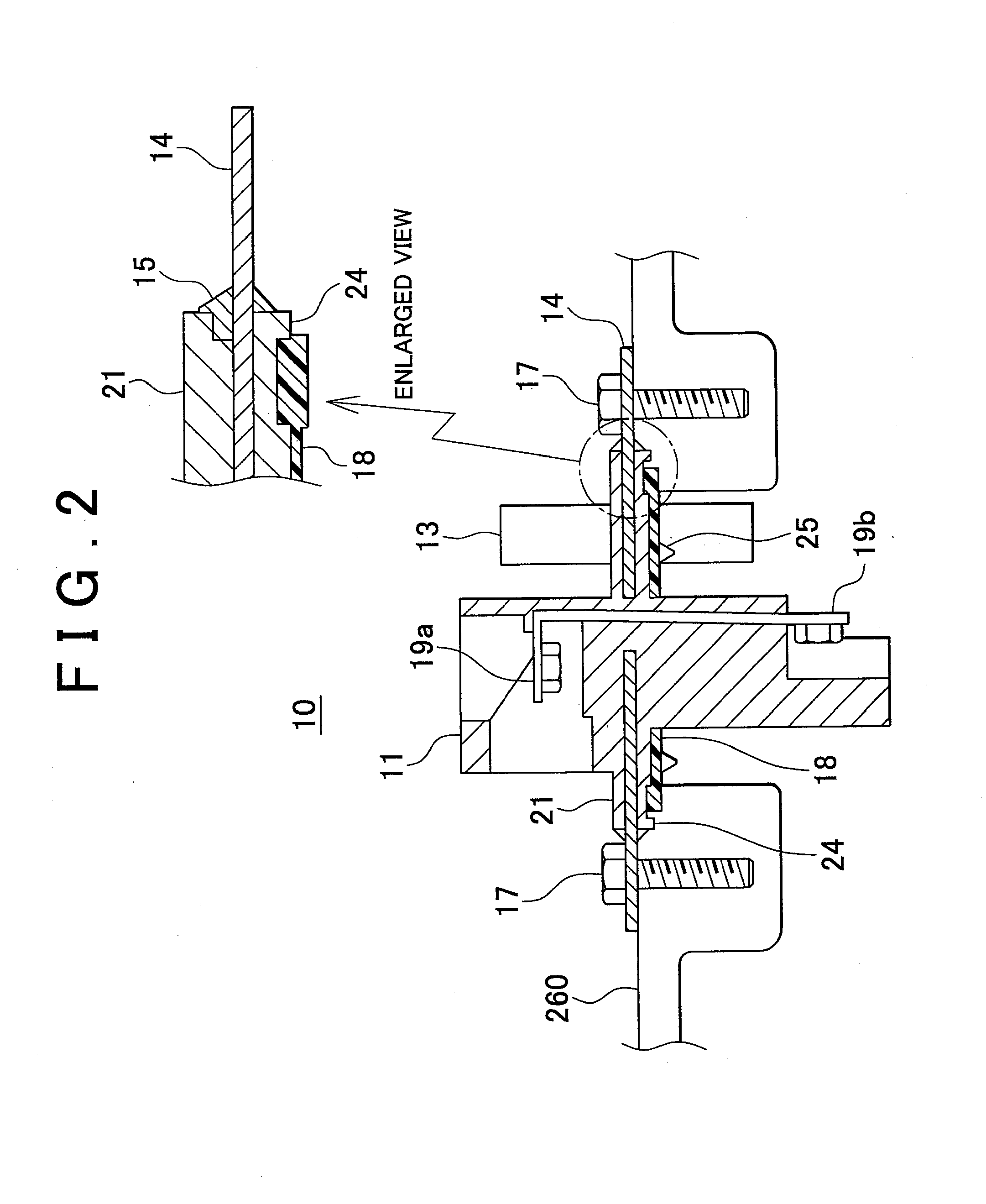
[0040]FIG. 1 shows a rotary electric machine terminal block 10 in accordance with the Incidentally, the rotary electric machine terminal block 10 is connected to an electricity generator unit; specifically, the rotary electric machine terminal block 10 is fitted into an opening of a case that contains a rotary electric machine, and is fixed to the case by a plate 14. The rotary electric machine terminal block 10 has: a mount that is formed by fixing an electric power line connector 11 and a signal line connector 13 to the steel-made plate 14 and then performing insert molding so that an anti-vibration portion 21 is formed on an upper surface of the plate 14; a projected portion of the plate 14 which has fixation holes for fixing the rotary electric machine terminal block 10 to the case; an edge seal member 15 covering an edge of the projected portion; and a face seal member 18 that achieves tight attachment between the case and the mount.

[0041]One of the features of a rotary electr...

second embodiment

[0048]FIG. 6 shows a front view of a rotary electric machine terminal block 20 in accordance with a second embodiment, and FIG. 7 shows a side view thereof, and FIG. 8 shows a bottom view thereof. The rotary electric machine terminal block 20 shown in FIG. 6 is connected to a rotary electric machine of an electric motor unit, and has an electric power line connector 11, a signal line connector 13, a plate 14, an edge seal member 15, and positioning pins 22 and 23. As shown in FIG. 7, an electric power bus cable is inserted into the rotary electric machine terminal block 20 in a direction B and another electric power bus cable is inserted thereinto in a direction A, and the two electric power bus cables are screwed to the electric power terminal plates, so that electric conduction between the two bus cables is secured.

[0049]Besides, one of the features of the embodiment is that partition plates 28 for setting a predetermined creepage distance are each provided between an electric pow...

third embodiment

[0050]FIG. 9 shows a rotary electric machine terminal block 30 in accordance with the invention. An anti-vibration portion 21 of the rotary electric machine terminal block 30 exposes an outer peripheral portion of the plate 14 and projected portions 14a to 14d projected from the outer peripheral portion of the plate 14. As shown in the enlarge view of the projected portion 14a in FIG. 19, the distance between the screwing position of projected portion 14a and the edge of the anti-vibration portion 21 is increased in this embodiment so as to reduce the amount of deformation of the plate 14 that occurs at the edge of the anti-vibration portion 21 and therefore prevent formation of a gap at the edge of the anti-vibration portion 21. Thus, this embodiment eliminates the need for an edge seal member, and further reduces the number of component parts. Incidentally, in this embodiment, an outer peripheral portion of the plate 14 is provided with through holes 26 of several millimeters in d...


PUM


Abstract

A rotary electric machine terminal block fits into an opening of a case that contains a rotary electric machine, and is fixed to the case by a plate. The rotary electric machine terminal block has: a mount that is formed by fixing the electric power line connector and the signal line connector to the steel-made plate and performing insert molding so that an anti-vibration plate is formed on an upper surface of the plate; projected portions of the plate which each have a fixture hole for fixing the plate to the case; an edge seal member that covers an edge of the projected portion; a face seal member for tight attachment of the mount to the case; and two positioning pins.

Description

INCORPORATION BY REFERENCE[0001]The disclosure of Japanese Patent Applications No. 2010-018496 and 2010-153337 filed on Jan. 29, 2010 and Jul. 5, 2010, respectively, including the specifications, drawings and abstracts, is incorporated herein by reference in its entirety.BACKGROUND OF THE INVENTION[0002]1. Field of the Invention[0003]The invention relates to a rotary electric machine terminal block provided on a transaxle case that contains a rotary electric machine. Particularly, the invention relates to a rotary electric machine terminal block whose size is reduced by adopting an insert molding process.[0004]2. Description of the Related Art[0005]There are generally known an electric motor vehicle propelled by electric power from a battery, a fuel cell motor vehicle propelled by electric power generated by a fuel cell, a hybrid motor vehicle propelled by a combination of an internal combustion engine and a rotary electric machine that functions as an electric motor or an electrici...

Claims


Application Information

Patent Timeline
Patent Type & Authority Applications(United States)
IPC IPC(8): H02K5/22
CPCH02K5/225
Inventor KITAGAWA, KATSUHIDEUEKI, KATSUNORIAKUTA, DAISUKEMATSUOKA, HIROYUKI
Owner TOYOTA JIDOSHA KK
Why Eureka
Try Eureka