

Resonant liquid densimeter structure
A densitometer and resonant technology, which is applied in the structural field of a resonant liquid density meter, can solve the problems of low measurement accuracy and achieve high precision and easy use
Inactive Publication Date: 2014-10-15
范明军
View PDF8 Cites 0 Cited by
- Summary
- Abstract
- Description
- Claims
- Application Information
AI Technical Summary
Problems solved by technology
[0003] The resonant tube densitometer in the prior art requires a strong drive to obtain the required resonant frequency of the vibrating tube due to the vibration of the vibrating tube, and the measurement accuracy is low
Method used
View moreImage
Smart ImageViewing Examples

Examples
specific Embodiment
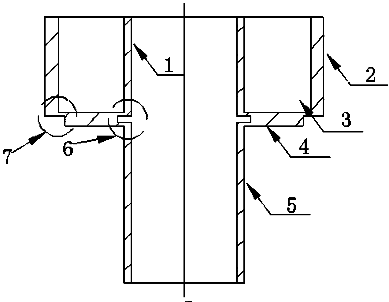
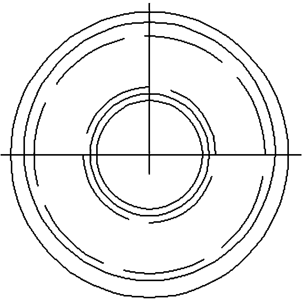
[0019] like figure 1 , figure 2 As shown, the inner wall between the vibration tube and the circuit protection inner tube is processed with a rectangular groove, and the outer edge of the lower surface of the bottom wall of the excitation / vibration pickup cavity is provided with a concave step. The wall thickness of the circuit protection inner tube is the same as that of the vibrating tube, and the error is not more than 1mm
[0020] The vibration excitation and vibration pickup components are placed in the vibration excitation / vibration pickup cavity formed by the circuit protection outer tube, the circuit protection inner tube and the bottom wall, and are completely isolated from the liquid.
Login to View More PUM
 Abstract
The invention discloses a resonant liquid densimeter structure, comprising a vibration excitation / vibration pickup cavity consisting of an outer circuit protection tube, an inner circuit protection tube and a bottom wall, wherein a vibration excitation and vibration pickup element is arranged in the vibration excitation / vibration pickup cavity, a vibration tube is connected to the lower part of the inner circuit protection tube, and rectangular grooves are machined in the inner wall between the vibration tube and the inner circuit protection tube. The outer edge of the lower surface of the bottom wall is provided with concave steps. The inner circuit protection tube and the vibration tube are concentric and identical in diameter and wall thickness, and the error of the wall thickness is smaller than or equal to 1mm. In the case that the vibration excitation / vibration pickup cavity drives, the vibration tube is very easy to vibrate, and then density of liquid to be measured can be obtained by measuring resonant frequency of the vibration tube.
Description
technical field [0001] The invention relates to a resonant cylinder density meter, in particular to a structure of a resonant liquid density meter. Background technique [0002] There are many forms of resonant densitometers, among which the resonant cylinder densitometer is the main form. [0003] The resonant tube densitometer in the prior art requires a strong drive to obtain the required resonant frequency of the vibrating tube due to the vibration of the vibrating tube, and the measurement accuracy is low. Contents of the invention [0004] The object of the present invention is to provide a structure of a resonant liquid density meter which is easy to drive and has high precision. [0005] The purpose of the present invention is achieved through the following technical solutions: [0006] The structure of the resonant liquid density meter of the present invention includes an excitation / vibration pickup cavity composed of a circuit protection outer tube, a circuit p...
Claims
Login to View More Application Information
Patent Timeline
 Patent Type & Authority Applications(China)
IPC IPC(8): G01N9/00
Inventor 范明军夏惠芳陈金瓶徐顺福刘时雨尹永亮
Owner 范明军