Wireless transmission system

A wireless transmission and subsystem technology, applied in the field of wireless transmission systems, can solve problems such as hard-to-control line erection

Inactive Publication Date: 2014-10-15
YALONG INTELLIGENT EQUIP GRP CO LTD
View PDF6 Cites 2 Cited by
  • Summary
  • Abstract
  • Description
  • Claims
  • Application Information

AI Technical Summary

Problems solved by technology

[0005] The main purpose of the present invention is to provide a wireless transmission system to solve the problem that it is difficult to set up control lines at industrial sites

Method used


Image

  • Wireless transmission system
  • Wireless transmission system
  • Wireless transmission system

Examples


Embodiment Construction

[0028] It should be noted that, in the case of no conflict, the embodiments in the present application and the features in the embodiments can be combined with each other. The present invention will be described in detail below with reference to the accompanying drawings and examples.

[0029] In order to enable those skilled in the art to better understand the solutions of the present invention, the following will clearly and completely describe the technical solutions in the embodiments of the present invention in conjunction with the drawings in the embodiments of the present invention. Obviously, the described embodiments are only It is an embodiment of a part of the present invention, but not all embodiments. Based on the embodiments of the present invention, all other embodiments obtained by persons of ordinary skill in the art without making creative efforts shall fall within the protection scope of the present invention.

[0030] It should be noted that the terms "fir...


PUM


Abstract

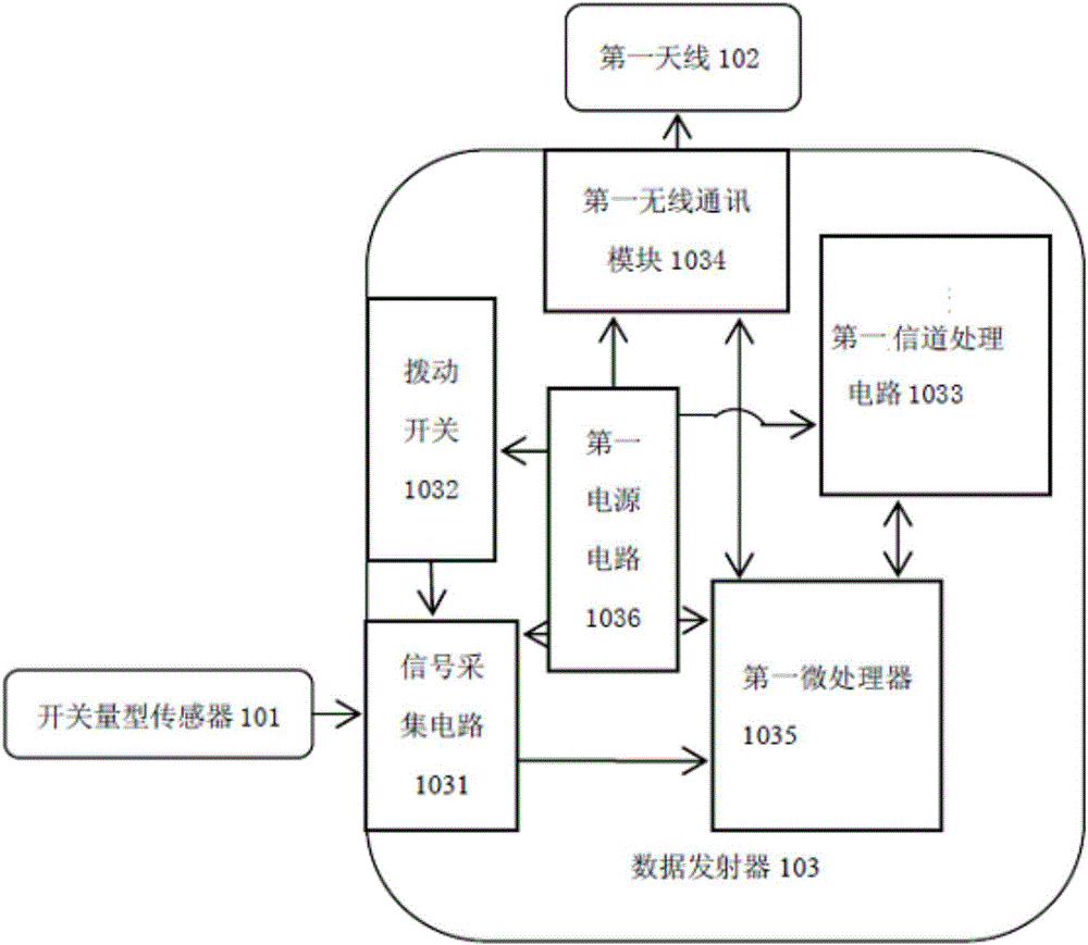
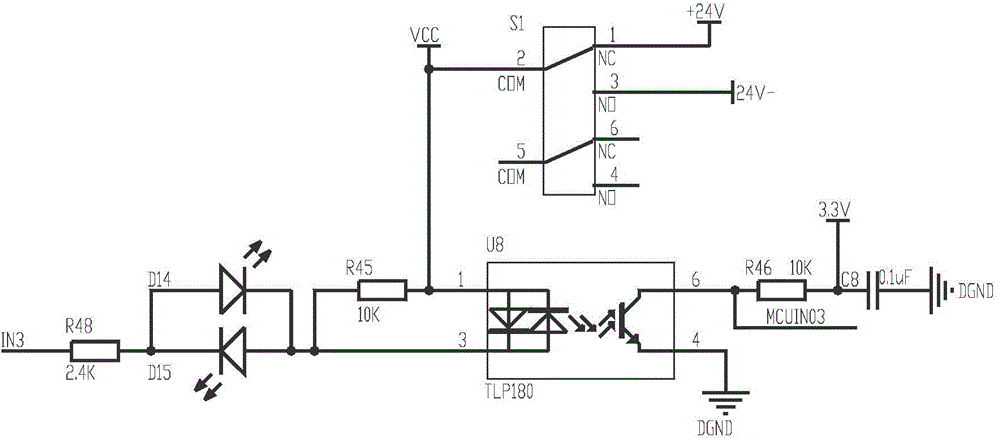
The invention discloses a wireless transmission system which is used for signal transmission of a switching value type sensor. The wireless transmission system comprises an emitting subsystem and a receiving subsystem, wherein the emitting subsystem comprises the switching value type sensor for outputting a switching value signal, a first antenna for emitting a signal as well as a data transmitter which is connected with the switching value type sensor and the first antenna respectively and used for receiving the switching value signal and emitting the switching value signal through the first antenna; the receiving subsystem comprises a second antenna for receiving the signal emitted by the first antenna and a data receiver which is connected with the second antenna and used for processing the signal received by the second antenna and acquiring and outputting processed data. According to the wireless transmission system, field routing is not required.

Description

technical field [0001] The present invention relates to the communication field, in particular, to a wireless transmission system. Background technique [0002] Wireless communication systems have been widely used in various fields, especially in fields requiring remote data communication. In the field of industrial control, computer technology, microcontroller programming technology, and peripheral electronic components are usually used to collect and transmit various industrial control signals in the industrial environment to control various industrial equipment that needs to be controlled. [0003] Since the control terminal usually adopts wired transmission to collect the data detected by the sensors on the industrial site, in order to avoid remote wiring, the control terminal is usually installed near the industrial site and is relatively close to the industrial site. However, due to the complex environment of the industrial site, it is difficult to erect control lines...

Claims


Application Information

Patent Timeline
IPC IPC(8): G08C17/02
Inventor 唐灿耿郑玉鑫余家泽徐鑫奇崔旭升
Owner YALONG INTELLIGENT EQUIP GRP CO LTD
Why Eureka
Try Eureka