Variable cross-section cantilever bridge box girder self-locking synchronization pushing system and construction method

A bridge box girder and variable cross-section technology, which is applied in bridges, bridge construction, erection/assembly of bridges, etc., can solve the problems of large loss of slide plates, low reuse rate, and increased cost

Active Publication Date: 2015-04-15
EAST STEEL STRUCTURE BRIDGE
View PDF8 Cites 0 Cited by
  • Summary
  • Abstract
  • Description
  • Claims
  • Application Information

AI Technical Summary

Problems solved by technology

[0004]1. The traction force cannot be counteracted by itself, and will act horizontally along the bridge direction on the temporary independent supports and bridge piers;
[0005]2. The bottom plate of the bridge box girder slides on the fixed-height sliding bearing. The bottom surface of the bridge is not flat due to the camber, and the sliding bearing cannot To adapt to the constantly changing elevation of the bridge bottom;
[0006]3. The sliding bearing cannot limit the lateral position of the bridge body, and a lateral jack is required to correct the deviation;
[0007]4. The loss of the skateboard is large, the reuse rate is low, and manual feeding is required;
[0008]5. The location of the sliding bearing is not flexible, and cannot meet the installation requirements of variable cross-section bridge box girders
But there are still the following disadvantages: it is necessary to process the tooth plate with tooth grooves and the slider at the end of the piston rod of the jacking jack, and the tooth plate needs to be removed after the pushing is completed, which increases the cost

Method used


Image

  • Variable cross-section cantilever bridge box girder self-locking synchronization pushing system and construction method
  • Variable cross-section cantilever bridge box girder self-locking synchronization pushing system and construction method
  • Variable cross-section cantilever bridge box girder self-locking synchronization pushing system and construction method

Examples


Embodiment Construction

[0045] The present invention will be further described below in conjunction with the drawings.

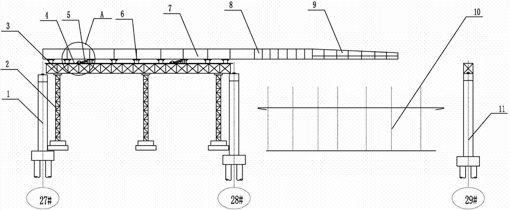
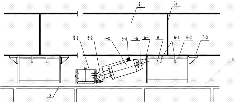
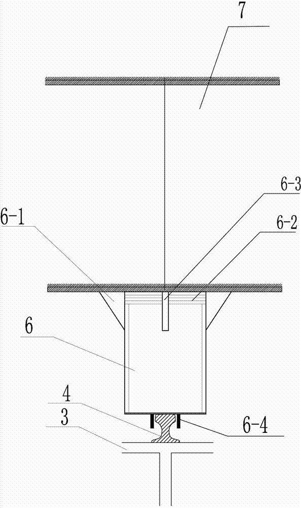
[0046] Such as Figure 1-4 As shown, the self-locking synchronous pushing system for box girder of variable cross-section cantilever bridge of the present invention includes a welding assembly platform system for pushing sliding bridge box girder arranged on the side of the railway, and the welding assembly platform for pushing sliding bridge box girder The system consists of a temporary support pier 2, a pushing sliding bridge box girder welding assembly platform 3 set on the temporary support pier 2, and a sliding track 4 set on the pushing sliding bridge box girder welding assembly platform 3 It consists of installing a set of sliding shoes 6 and a set of self-locking synchronous pushing devices 5 on the sliding track 4, and the set of self-locking synchronous pushing devices 5 are electrically connected to the automatic pushing control system. Features are:

[0047] The self-loc...


PUM


Abstract

The invention relates to a self-locking synchronous jacking system and a construction method for a box girder of a variable-section cantilever bridge, comprising a welding and assembling platform system for a box girder of a sliding bridge, a sliding track, a set of sliding shoes and a set of sliding shoes installed on the sliding track. Self-locking synchronous jacking device, automatic control of jacking, characterized in that: the self-locking synchronous jacking device includes a hydraulic jacking cylinder and a self-locking jacking rail clamp, which is installed on the upper part of the sliding shoe For adjusting pads for adjusting the arch of the bridge, a thrust plate and a side limit plate are respectively arranged on the front and side of the sliding shoe to prevent the sliding of the sliding shoe when pushing, and on the lower part of the sliding shoe and Track limit plates are set on both sides of the track contact part to limit the offset of the sliding shoe. The bridge box girder is placed on the upper part of the slide shoe. The front end of the bridge box girder of the first section is provided with a bridge box girder transition section and a guide beam. The construction method of the self-locking synchronous jacking system of the box girder of the variable-section cantilever bridge of the present invention effectively solves the problem of bridge erection across complex environments such as railways, and is safe, reliable and efficient.

Description

technical field [0001] The invention relates to bridge box girder construction equipment and a bridge box construction method thereof, in particular to a variable-section cantilever bridge box girder self-locking synchronous jacking system and a construction method. Background technique [0002] The construction of urban rapid interchange bridges in China is in full swing. Steel structure bridges are widely used in the construction of long-span bridges at home and abroad due to their light structure, high strength, fast installation, and various shapes. Existing obstacles such as intersections or railways Most of the bridges are installed by erecting temporary supports. Because the trains need to run normally, the cross-railway bridges cannot support the tire frame installation, so they can only be installed by the sliding method. The ordinary sliding method is installed by the pulling method. , the traction force of this scheme should be transmitted to the temporary pillars...

Claims


Application Information

Patent Timeline
Patent Type & Authority Patents(China)
IPC IPC(8): E01D21/06
Inventor 郑永会孙宇凡尚瞳
Owner EAST STEEL STRUCTURE BRIDGE
Why Eureka
Try Eureka