Logic level signal transmitting method and device

A technology of logic level and signal transmission, applied in the field of signal transmission, to achieve the effect of reducing the number of pins, reducing the difficulty of structural design, and improving reliability

Active Publication Date: 2014-10-15
FORYOU GENERAL ELECTRONICS
View PDF5 Cites 0 Cited by
  • Summary
  • Abstract
  • Description
  • Claims
  • Application Information

AI Technical Summary

Problems solved by technology

[0004] The invention provides a logic level signal transmission method and device, which solves the technical problem of using one signal line to complete two logic level signal transmissions

Method used


Image

  • Logic level signal transmitting method and device
  • Logic level signal transmitting method and device
  • Logic level signal transmitting method and device

Examples


Embodiment 1

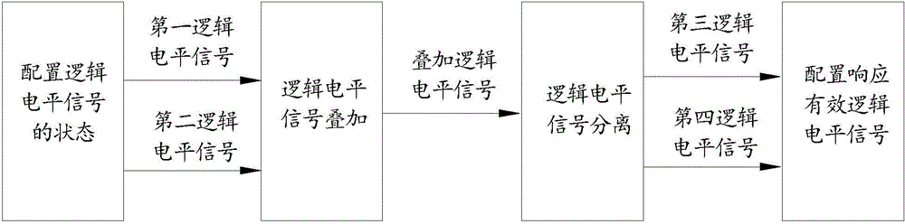
[0044] like figure 1 As shown, this embodiment provides a logic level signal transmission method, including: generating a superimposed logic level signal after superimposing the transmitted first logic level signal and the second logic level signal, and superimposing the superimposed logic level signal After the flat signal is transmitted, it is separated into a third logic level signal and a fourth logic level signal, and the third logic level signal or the fourth logic level signal is received in response;

[0045] The first logic level signal and the second logic level signal are respectively the same as the third logic level signal and the fourth logic level signal, and the transmission of the second logic level signal is performed after the transmission of the first logic level signal is completed.

[0046] In an embodiment of the present invention, before the above logic level signal transmission step, it also includes:

[0047] The first logic level signal and the seco...

Embodiment 2

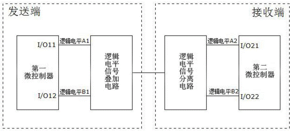
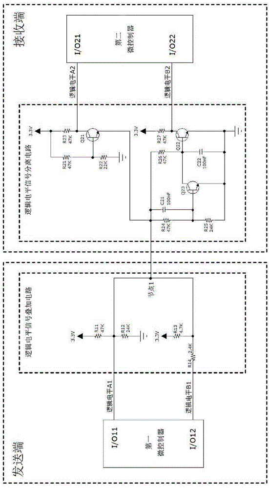
[0056] like figure 2 As shown, this embodiment provides a logic level signal transmission device, including a first set of signal input and output interfaces, a logic level signal superposition circuit, a logic level signal separation circuit, and a second set of signal input and output interfaces;

[0057] The first group of signal input and output interfaces includes a first logic level signal output interface I / O11 and a second logic level signal output interface I / O12, respectively connected to the first logic level signal input terminal and the logic level signal superposition circuit of the logic level signal The second logic level signal input terminal is used to send the first logic level signal and the second logic level signal to the logic level signal superposition circuit;

[0058] A logic level signal superposition circuit, configured to superimpose the first logic level signal and the second logic level signal to generate a superimposed logic level signal, and t...

Embodiment 3

[0088] In this example, if Figure 4 As shown, the difference between this embodiment and Embodiment 2 is that another structure of the logic level signal transmission device is provided:

[0089] The first group of signal input and output interfaces are connected to a switch S11, and the first logic level signal or the second logic level signal sent through the switch S11 is controlled to change from a normal logic level signal to an effective logic level signal.

[0090] The logic level signal transmission device provided in this embodiment can be applied to a car entertainment navigation system in the form of a split machine, specifically for signal transmission between the host and the panel of the split machine, such as the MCU on the host and the panel The transmission of the mechanical reset signal for the overall reset of the MPU and the software reset signal for the MPU reset on the panel is transmitted successively by using one signal line in this embodiment, and doe...


PUM


Abstract

The invention provides a logic level signal transmitting method and device. The method comprises the steps that a transmitted first logic level signal and a transmitted second logic level signal are superposed to generate a superposed logic level signal, the superposed logic level signal is transmitted and then is separated into a third logic level signal and a fourth logic level signal, and the third logic level signal or the fourth logic level signal is responded and received; the first logic level signal and the second logic level signal are identical with the third logic level signal and the fourth logic level signal respectively, and the second logic level signal is transmitted after the first logic level signal is transmitted. According to the logic level signal transmitting method and device, the two paths of logic level signals are superposed and transmitted, and then are separated into the two paths of logic level signals, the two paths of logic level signals are transmitted through one signal line, the number of pins of a connector between a fission machine host and a display screen of a vehicle-mounted entertainment navigation system is reduced, the structural design difficulty is lowered, and the reliability of signal connection is improved.

Description

technical field [0001] The present invention relates to the technical field of signal transmission, in particular to a logic level signal transmission method and device. Background technique [0002] In the current car entertainment navigation system, there are more and more split machines in which the main unit and the panel are separated, and the two are electrically connected by cables; generally, the main unit contains MCU and related circuits, and the panel contains MPU and related circuits. However, there are many signals connected to each other between the main unit and the panel of the split machine, including audio and video, control, communication and other signals, so that the pin PIN of the connector used must be enough, which makes it difficult to select the connector. The structural design also becomes complicated, which in turn reduces the reliability of the signal connection of the split machine. [0003] Among the connection signals of the split machine, t...

Claims


Application Information

Patent Timeline
IPC IPC(8): H03K19/0175
Inventor 陈守和刘凌云
Owner FORYOU GENERAL ELECTRONICS
Why Eureka
Try Eureka