
Serial communication method of servo driver, and servo driver

A servo driver and serial communication technology, applied in the field of servo drivers, can solve the problems of increased cost, increased layout design complexity, increased chip pins, etc., and achieve the effects of reducing hardware costs, saving space, and flexible usage scenarios

Pending Publication Date: 2019-04-05
庸博(厦门)电气技术有限公司
View PDF0 Cites 0 Cited by
  • Summary
  • Abstract
  • Description
  • Claims
  • Application Information

AI Technical Summary

Problems solved by technology

[0003] At present, mainstream servo drives generally have multiple cores, among which the control core usually adopts a digital signal processor (DSP), which can realize relatively complex control algorithms, realize digital, network and intelligent processing, and other programmable devices are used as auxiliary The function core, the control core and other auxiliary function cores need to transmit data through communication. At present, the commonly used communication method is parallel communication. Since it transmits data through parallel transmission of multiple data bits at the same time, it can be increased by adding The number of bits of data transmitted at the same time is used to improve the transmission bandwidth, but in the design of the servo driver, when the number of data bits to be transmitted increases continuously, it leads to an increase in the number of chip pins that need to be occupied, not only the PCB layout design is complicated. increase and also lead to an increase in cost

Method used


Image

  • Serial communication method of servo driver, and servo driver
  • Serial communication method of servo driver, and servo driver

Examples


Embodiment Construction

[0038] The following will clearly and completely describe the technical solutions in the embodiments of the present invention with reference to the accompanying drawings in the embodiments of the present invention. Obviously, the described embodiments are only some, not all, embodiments of the present invention. Based on the embodiments of the present invention, all other embodiments obtained by persons of ordinary skill in the art without creative efforts fall within the protection scope of the present invention.

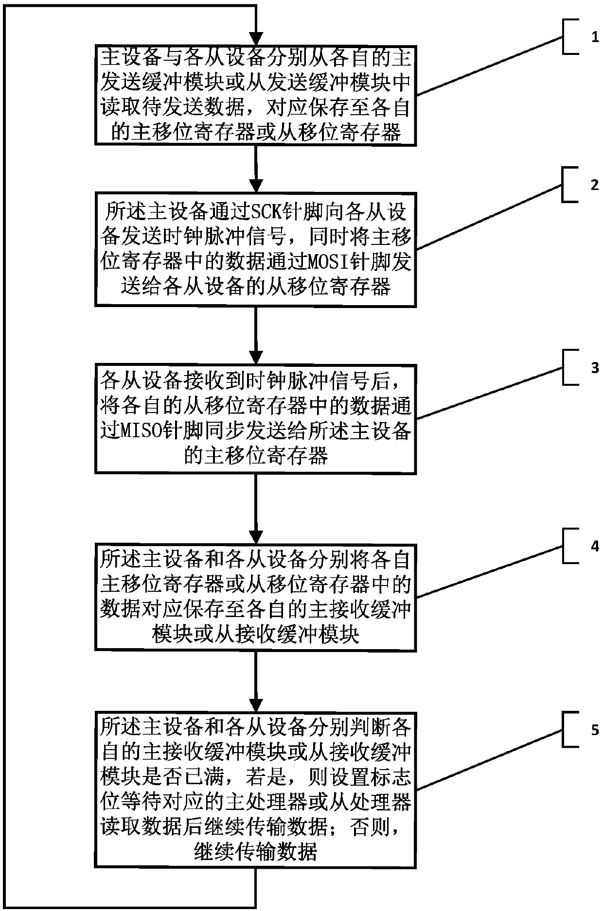
[0039] like figure 1 , is a flowchart of steps of a serial communication method of a servo driver of the present invention, comprising the following steps:

[0040] Step 1. The master device and each slave device respectively read the data to be sent from their respective master sending buffer modules or slave sending buffer modules, and store them in their respective master shift registers or slave shift registers;

[0041] In a servo driver, it usually contains ...


PUM


Abstract

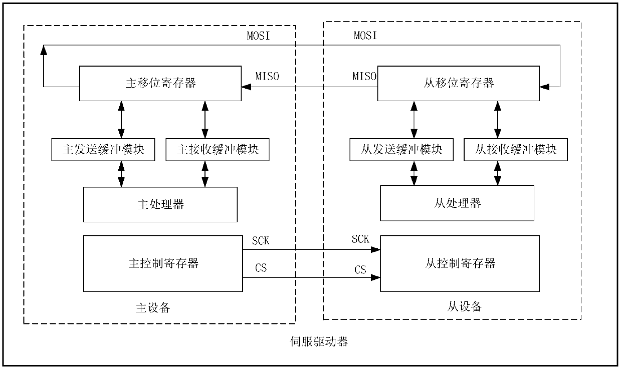
The invention belongs to the technical field of the industrial control, and specifically relates to a serial communication method of a servo driver, and the servo driver. The serial communication method comprises the following steps: each of master equipment and slave equipment reads to-be-sent data from the own sending buffer module, and saves the to-be-sent data to the own shifting register; themaster equipment sends a clock pulse signal to the slave equipment, and sends the data in the main shifting register to the slave shifting register of each set of slave equipment; after receiving theclock pulse signal, each set of slave equipment synchronously sends the data in the slave shifting register to the main shifting register; each of the master equipment and the slave equipment saves the data in the shifting register to the corresponding receiving buffering module; if a main receiving buffering module or the slave receiving buffering is already full, a zone bit is set so as to continuously transmit data after a processor reads the data; above steps are repeated to realize the serial transmission of the data between the master equipment and the slave equipment. An amount of thepin between the master equipment and the slave equipment can be saved through the scheme disclosed by the invention, the layout space of the PCB can be saved, and the hardware cost is reduced.

Description

technical field [0001] The invention belongs to the technical field of industrial control, and in particular relates to a serial communication method of a servo driver and the servo driver. Background technique [0002] Servo drive, also known as servo controller, is a controller used to control servo motors. Its function is similar to that of frequency converters on ordinary AC motors. It is a part of the servo system and is mainly used in high-precision positioning systems. Servo drives generally control the servo motor through three methods of position, speed and torque to achieve high-precision positioning of the transmission system. It is currently a high-end product of transmission technology. Servo drives have become an important part of modern motion control and are widely used in automation equipment such as industrial robots and CNC machining centers. [0003] At present, mainstream servo drives generally have multiple cores, among which the control core usually a...

Claims


Application Information

Patent Timeline
IPC IPC(8): G05B19/042
CPCG05B19/0428G05B2219/2612
Inventor 卢国成陈明鸿周密
Owner 庸博(厦门)电气技术有限公司
Learn More