A synchronous rectifier turn-on control method and circuit

A technology of synchronous rectifier tubes and control circuits, which is applied in the direction of control/regulation systems, electrical components, and adjustment of electrical variables. It can solve the problems of limited voltage drop slope off time, long voltage drop time, and chip use restrictions, etc., to achieve Effects of reduced size and cost, increased reliability, and flexible design

Active Publication Date: 2019-04-19
MORNSUN GUANGZHOU SCI & TECH +1
View PDF6 Cites 0 Cited by
  • Summary
  • Abstract
  • Description
  • Claims
  • Application Information

AI Technical Summary

Problems solved by technology

However, in practical applications, the voltage drop slope at the beginning of degaussing is limited by the turn-off time of the primary power tube. Smaller, increasing the difficulty of detection
This limits the use of this chip

Method used


Image

  • A synchronous rectifier turn-on control method and circuit
  • A synchronous rectifier turn-on control method and circuit
  • A synchronous rectifier turn-on control method and circuit

Examples


Embodiment 1

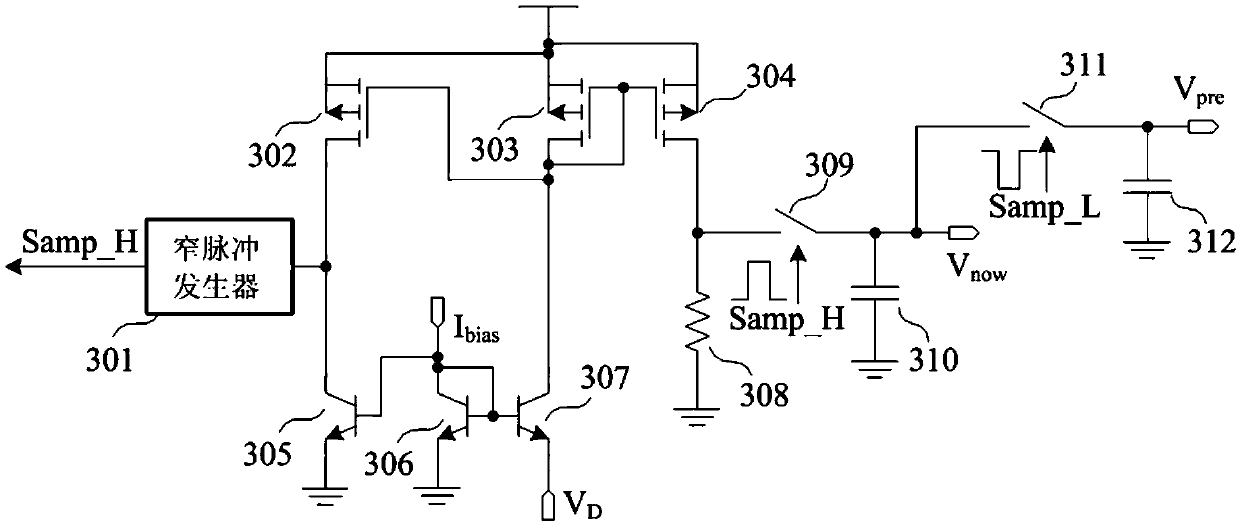
[0035] Such as image 3 As shown, it is the drain negative pressure sampling and holding circuit in the synchronous rectifier tube opening control circuit of the present invention, including narrow pulse generator 301, PMOS tube 302, PMOS tube 303, PMOS tube 304, NPN tube 305, NPN tube 306, NPN tube 307, resistor 308, switch 309, capacitor 310, switch 311, capacitor 312. The input terminal of the narrow pulse generator 301 is connected to the drain terminal of the PMOS transistor 302 and the collector of the NPN transistor 305, and the output terminal of the 301 provides the sampling signal Samp_H of each negative pressure; the source terminal of the PMOS transistor 302 is connected to the power supply , the gate terminal is connected to the drain of the PMOS transistor 303 and the collector of the NPN transistor 307; the emitter of the NPN transistor 305 is grounded, and the base is connected to the collector of the NPN transistor 306; the emitter of the NPN transistor 306 is...

Embodiment 2

[0041] Such as Figure 5 As shown, it is another structure of the drain negative pressure sample-and-hold circuit. Compared with the first embodiment, the capacitor 310 is removed, and the connection relationship between the switches 309 and 311 is changed, and other parts are the same as the first embodiment. One end of the switch 309 is connected to one end of the resistor 308, and the other end of the 309 does not need to be connected to a capacitor, and directly gives the voltage value of this sampling; one end of the switch 311 bypasses the switch 503, and is directly connected to one end of the resistor 308, and the other end of the 311 The capacitor 312 is connected to give the last sampled and saved voltage value, and the control terminal of 311 is connected to the delayed signal Samp_H2 of the sampling signal Samp_H. Samp_H2 is still a narrow pulse, which is generated by an external delay circuit, but it is delayed relative to Samp_H in time.

[0042] The Samp_H sig...

Embodiment 3

[0044] Such as Figure 6As shown, it is another structure of the drain negative pressure sample-and-hold circuit. The resistor 308 in Embodiment 1 is removed, and a third switch 601 is added; one end of the third switch 601 is connected to the upper plate of the capacitor 310 , the other end of 601 is grounded, and the control end of 601 is connected to the sampling signal Samp_H3 . The partial signal Samp_H3 of the sampling signal Samp_H first discharges the charge of the capacitor 310 to initialize the capacitor. The falling edge of the partial signal Samp_H3 arrives before the falling edge of Samp_H. During the period when Samp_H is at high level and Samp_H3 is at low level, the negative voltage is converted into current, and the capacitor 310 is charged through the PMOS transistor 304 . Thereafter, Samp_H becomes low level, and the inversion signal Samp_L becomes high level, the switch 311 is turned on, and the voltage on the capacitor 312 is refreshed. The capacitance ...


PUM


Abstract

The invention provides an isolation converter synchronization rectifying tube open control method and circuit; under a DCM mode, the synchronization rectifying tube drain end voltage negative voltage value gradually decreases from the demagnetization beginning moment to each resonance trough, so the demagnetization beginning moment can be determined, thus preventing synchronization rectification error-opening caused by the resonance trough. The advantages are that 1, no external pin is needed to regulate the synchronization rectifying tube open threshold and the minimum turn off time, thus adapting to different system requirements, reducing packaging sizes and costs, and improving usage simplicity; 2, compared a conventional mode in which the drain end voltage falling edge is detected, the method and circuit need not to consider primary side switch tube driving characteristics, and the primary side drive can be flexibly designed; 3, the synchronization rectifying tube drain end negative voltage gradually decreasing trend in a single cycle is the inherent characteristic of each system; signal internal processing is realized after sampling, thus improving the synchronization rectifying tube open control reliability.

Description

technical field [0001] The invention relates to a synchronous rectification circuit, in particular to a novel synchronous rectification control method and circuit, which is suitable for an isolated switching power supply. Background technique [0002] For the sake of electrical safety and avoiding interference with input sources, many electrical occasions require the use of transformer-isolated switching power supplies. In order to improve the overall efficiency of the power supply system, a synchronous rectification circuit is often used, and a synchronous switching tube is used to rectify the degaussing current. Assume that the on-resistance of the switch tube is R on , the voltage drop of the ordinary rectifier diode is V D , the degaussing current is I sec , then as long as I sec *R on <V D , there is an efficiency advantage in synchronous rectification. For isolated switching power supplies, the synchronous rectification function is implemented on the secondar...

Claims


Application Information

Patent Timeline
IPC IPC(8): H02M3/335H02M1/08
CPCH02M1/08H02M3/33592Y02B70/10
Inventor 於昌虎唐盛斌肖华
Owner MORNSUN GUANGZHOU SCI & TECH
Why Eureka
Try Eureka